Appendices
A-148
CJ2 CPU Unit Software User’s Manual
Note In CJ-series PLCs, the following flags are provided in a special read-only area and can be specified with the labels given
in the table. These flags are not contained in the Auxiliary Area. Refer to 6-21 Condition Flags and 6-22 Clock Pulses for
details.
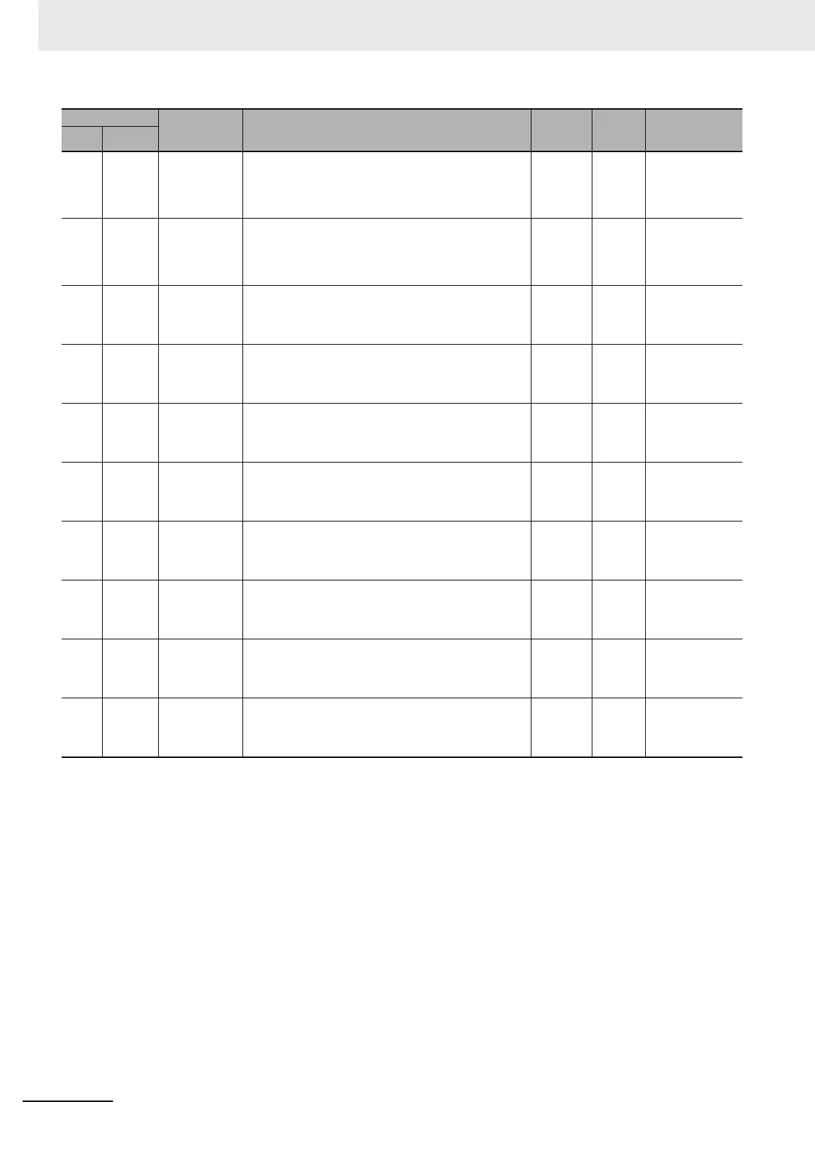
A10140
and
A10141
--- High-speed
Counter 2 Ring
Counter Maxi-
mum Value
Contain the ring counter maximum values when high-speed
counters 2 is used as ring counters. These values are cleared to 0
if Linear Mode is used.
Lower 4 digits: A10140, Upper 4 digits: A10141
Cleared Cleared Refreshed when
INI(880) instruction
is executed to
change ring counter
maximum value.
A10142
and
A10143
--- High-speed
Counter 3 Ring
Counter Maxi-
mum Value
Contain the ring counter maximum values when high-speed
counters 3 is used as ring counters. These values are cleared to 0
if Linear Mode is used.
Lower 4 digits: A10142, Upper 4 digits: A10143
Cleared Cleared Refreshed when
INI(880) instruction
is executed to
change ring counter
maximum value.
A10144
and
A10145
--- Interrupt input 0
latched PV
When there is an input for interrupt input 0, the PV of pulse output
0 or the PV of high-speed counter input 0 is stored. The PV imme-
diately before the interrupt input task is started is read and saved.
Lower 4 digits: A10144, Upper 4 digits: A10145
Cleared Cleared When input interrupt
occurs
A10146
and
A10147
--- Interrupt input 1
latched PV
When there is an input for interrupt input 1, the PV of pulse output
1 or the PV of high-speed counter input 1 is stored. The PV imme-
diately before the interrupt input task is started is read and saved.
Lower 4 digits: A10146, Upper 4 digits: A10147
Cleared Cleared When input interrupt
occurs
A10148
and
A10149
--- Interrupt input 2
latched PV
When there is an input for interrupt input 2, the PV of pulse output
2 or the PV of high-speed counter input 2 is stored. The PV imme-
diately before the interrupt input task is started is read and saved.
Lower 4 digits: A10148, Upper 4 digits: A10149
Cleared Cleared When input interrupt
occurs
A10150
and
A10151
--- Interrupt input 3
latched PV
When there is an input for interrupt input 3, the PV of pulse output
3 or the PV of high-speed counter input 3 is stored. The PV imme-
diately before the interrupt input task is started is read and saved.
Lower 4 digits: A10150, Upper 4 digits: A10151
Cleared Cleared When input interrupt
occurs
A10152
and
A10153
--- Interrupt input 4
latched PV
When there is an input for interrupt input 4, the PV of pulse output
4 or the PV of high-speed counter input 4 is stored. The PV imme-
diately before the interrupt input task is started is read and saved.
Lower 4 digits: A10152, Upper 4 digits: A10153
Cleared Cleared When input interrupt
occurs
A10154
and
A10155
--- Interrupt input 5
latched PV
When there is an input for interrupt input 5, the PV of pulse output
5 or the PV of high-speed counter input 5 is stored. The PV imme-
diately before the interrupt input task is started is read and saved.
Lower 4 digits: A10154, Upper 4 digits: A10155
Cleared Cleared When input interrupt
occurs
A10156
and
A10157
--- Interrupt input 6
latched PV
When there is an input for interrupt input 6, the PV of pulse output
6 or the PV of high-speed counter input 6 is stored. The PV imme-
diately before the interrupt input task is started is read and saved.
Lower 4 digits: A10156, Upper 4 digits: A10157
Cleared Cleared When input interrupt
occurs
A10158
and
A10159
--- Interrupt input 7
latched PV
When there is an input for interrupt input 7, the PV of pulse output
7 or the PV of high-speed counter input 7 is stored. The PV imme-
diately before the interrupt input task is started is read and saved.
Lower 4 digits: A10158, Upper 4 digits: A10159
Cleared Cleared When input interrupt
occurs
Address
Name Function
Status
after mode
change
Status at
startup
Write timing/
Related flags, set-
tings
Words Bits