Section 10 Transferring Data 10-1 Transferring Data to the PT
NS-Designer Operation Manual
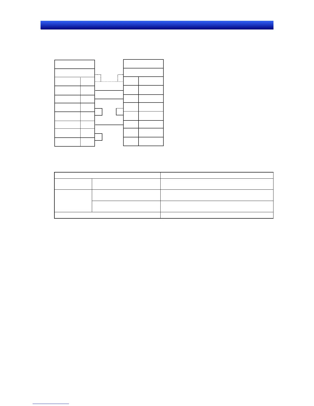
Connecting the PT to a Modem
After completing the modem settings, connect the PT to the modem. Use the following connection dia-
gram as reference and connect the PT to the modem.
Modem
Connector hood (FG)
FG
SD
RD
RS
CS
SG
DR
ER
1
2
3
4
5
6
7
20
PT
Connector hood (FG)
FG
SD
RD
RS
CS
SG
DR
ER
1
2
3
4
5
9
7
8
D-sub 25-pin connector (male)
D-sub 9-pin connector (male)
Shield
Preparations for Transferring Data via Controller Link
The following hardware is required to transfer data via Controller Link.
Name Model
PT Computer Link Interface Unit
(See note 1.)
NS-CLK21
Controller Link Support Board for
ISA Bus (See note 2.)
3G8F5-CLK21 Computer
Controller Link Support Board
(See note 3.)
3G8F7-CLK21
Twisted-pair Cable ESVC0.5X2C
Note 1. Refer to 3-8 Installing the Controller Link Interface Unit in the NS Series Setup Manual (Cat. No. V083)
for information on mounting and wiring the NS-CLK21 Controller Link Interface Unit.
2. Refer to the Controller Link Support Boards Operation Manual (Cat. No. W307) for information on
mounting and setting the NS-CLK21 Controller Link Support Board for ISA Bus.
3. Refer to the Controller Link Support Boards for PCI Bus Operation Manual (Cat. No. W383) for infor-
mation on mounting and setting the NS-CLK21 Controller Link Support Board for PCI Bus.
Settings before Transferring Data via Controller Link
PT Settings
The following settings must be made from the NS-Designer before transferring screen data to a PT
connected via Controller Link. After the settings have been made, they are transferred to the PT along
with any screen data without using the Controller Link.
1. Select Settings – System Settings – Comm – All from the NS-Designer.
2. Set Controller Link to Use.
3. Click the Controller Link Tab and make the following settings. Set the network address of the
Controller Link to which the PT is connected. The setting range is from 1 to 127.
4. Set the node address to the node address of the PT in the Controller Link network. The setting
range is from 1 to 32.
5. Set the baud rate to 500 Kbps, 1 Mbps, or 2 Mbps.
6. Click the OK Button.
10-6