3-12
3-1 Servo Drive Specifications
3
Specifications
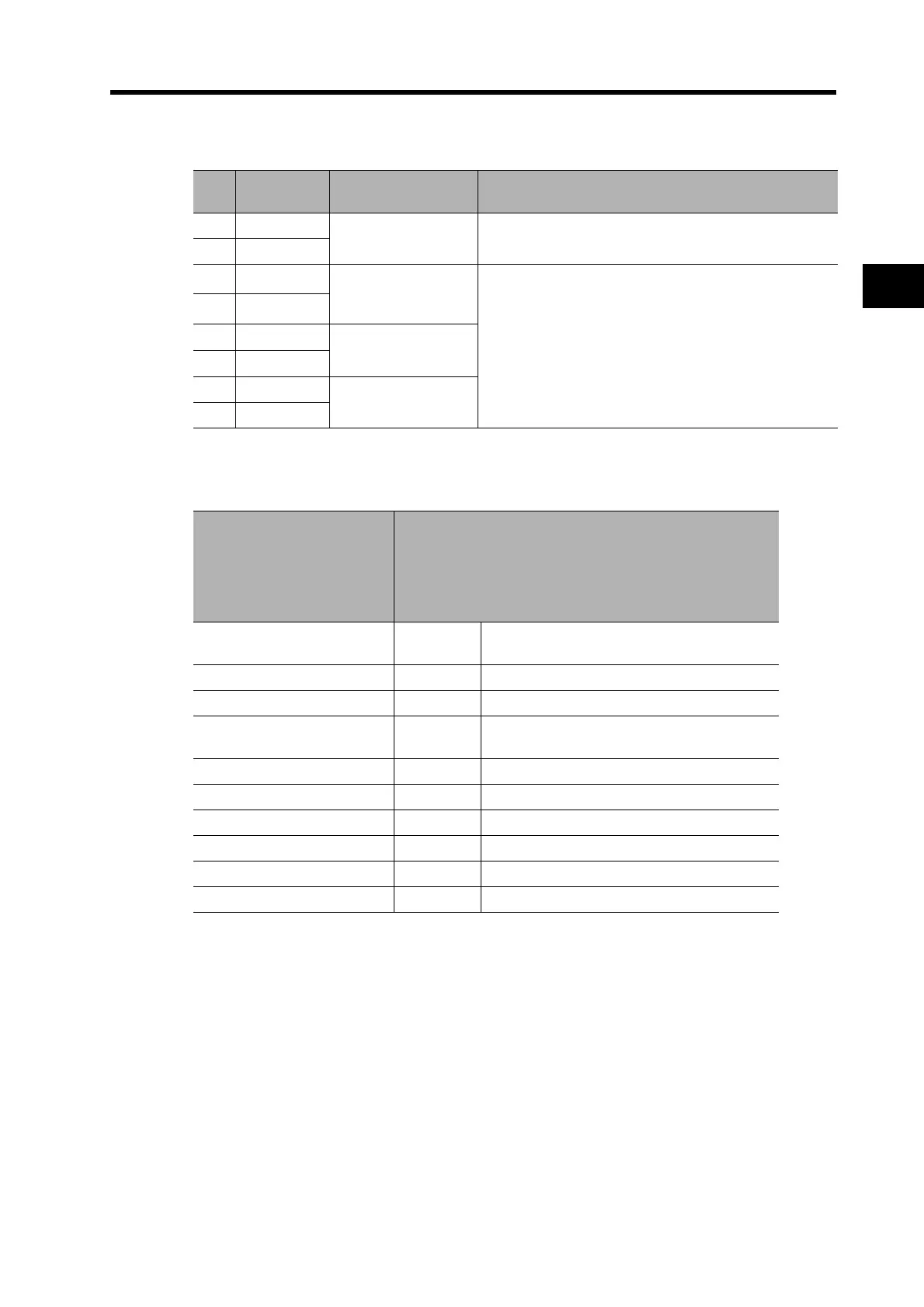
CN1 Control Output Signals
Output Signal Assignment Details
Pin
No.
Symbol Name Function/Interface
15 /ALM
Alarm Output
The output is OFF when an alarm is generated in the Ser-
vo Drive.
16 ALMCOM
29 OUTM2
General-purpose
Output 2 (READY)
This is a general-purpose output. The function for this
output is selected by changing the parameter.
Refer to the Output Signal Assignment Details below.
30 OUTM2COM
31 OUTM3
General-purpose
Output 3 (CLIM)
32 OUTM3COM
36 OUTM1
General-purpose
Output 1 (BKIR)
35 OUTM1COM
Pn112 (General-purpose
Output 1 Function Selection)
Pn113 (General-purpose
Output 2 Function Selection)
Pn114 (General-purpose
Output 3 Function Selection)
OUTM1 (General-purpose Output 1)
OUTM2 (General-purpose Output 2)
OUTM3 (General-purpose Output 3)
0
Not
assigned
No output. Always OFF.
1 INP1 Positioning Completed 1 output assignment.
2 VCMP Speed Conformity Signal output assignment.
3TGON
Servomotor Rotation Speed Detection output
assignment.
4 READY Servo Ready output assignment.
5 CLIM Current Limit Detection output assignment.
6 VLIM Speed Limit Detection output assignment.
7 BKIR Brake Interlock output assignment.
8 WARN Warning Signal output assignment.
9 INP2 Positioning Completed 2 output assignment.
 Loading...


