3-13
3-1 Servo Drive Specifications
3
Specifications
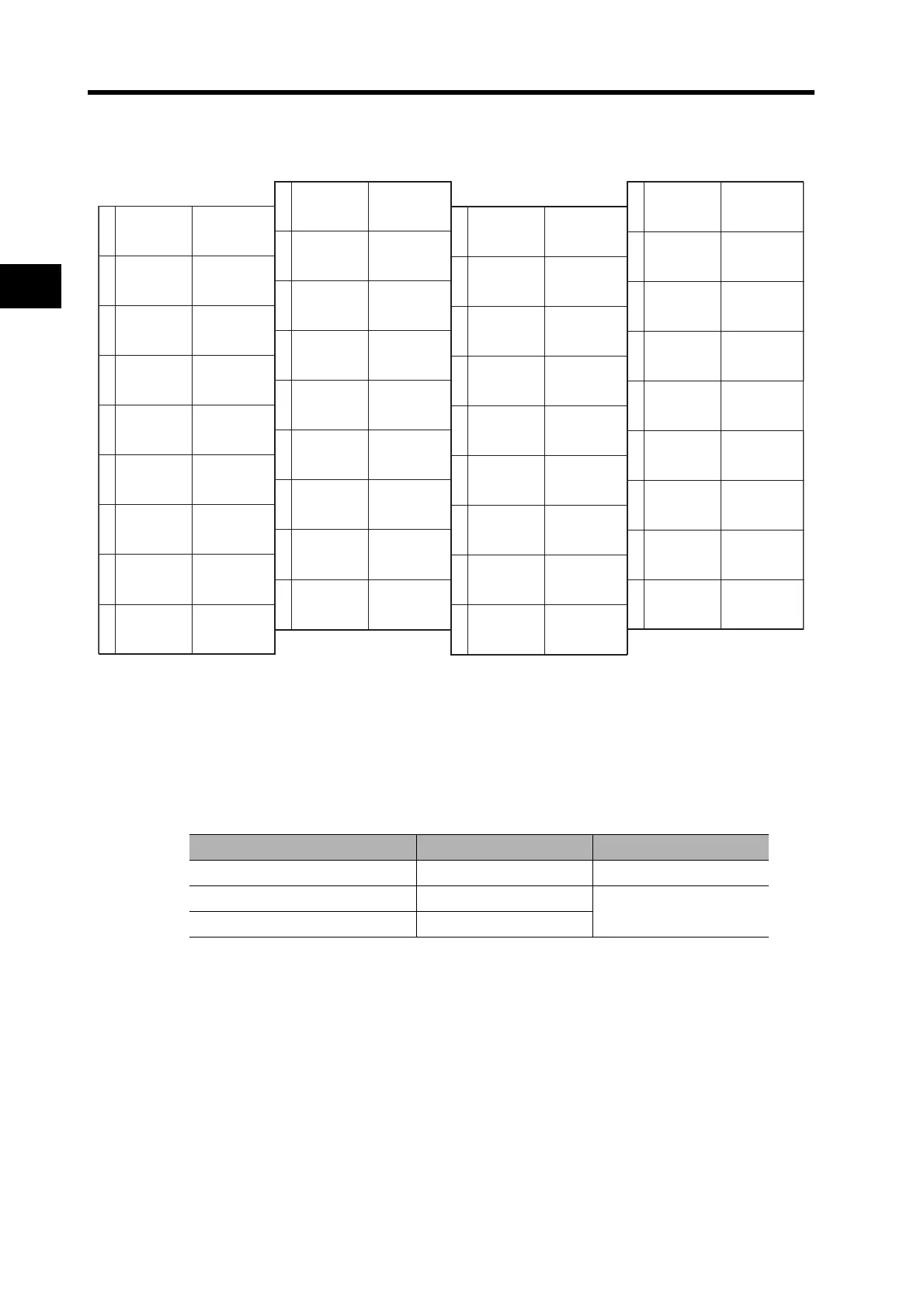
CN1 Pin Arrangement
Note1. Do not connect anything to unused pins (*).
Note2. Inputs for pins 19 and 20 are determined by parameter settings. The diagram shows the default
configuration.
Connector for CN1 (36 Pins)
Name Model Manufacturer
Servo Drive Connector 52986-3679 Molex Japan
Cable Connector 10136-3000PE
Sumitomo 3M
Cable Case (Shell Kit) 10336-52A0-008
2
4
6
8
10
12
14
16
18
20
22
24
12 to 24-VDC
Power Supply
Input
Emergency
Stop Input
+24VIN1
3
5
7
9
11
13
15
17
19
21
23
25
27
29
31
33
35
26
28
30
32
34
36
POT
IN1
Forward Drive
Prohibit Input
EXT3
Reverse Torque
Limit Input
NOT
STOP
DEC
IN0
Origin Proximity
Input
OUTM2
General-purpose
Output 2
BAT
Backup Battery
Input
BATCOM
ALMCOM
Alarm Output
/ALM
Alarm Output
NCL
PCL
External Latch
Signal 3
Reverse Drive
Prohibit Input
External
General-purpose
Input 0
Forward Torque
Limit Input
External
General-purpose
Input 1
EXT2
External Latch
Signal 2
EXT1
External Latch
Signal 1
*
*
*
*
*
*
*
IN2
External
General-purpose
Input2
*
*
OUTM2COM
General-purpose
Output 2
OUTM3
General-purpose
Output 3
OUTM3COM
General-purpose
Output 3
Backup Battery
Input
OUTM1COM
General-purpose
Output1
OUTM1
General-purpose
Output 1
*
*
*
*

 Loading...


