4-11
4-1 Installation Conditions
System Design
4
Installing an R88G-VRSF (Backlash = 15’ Max.)
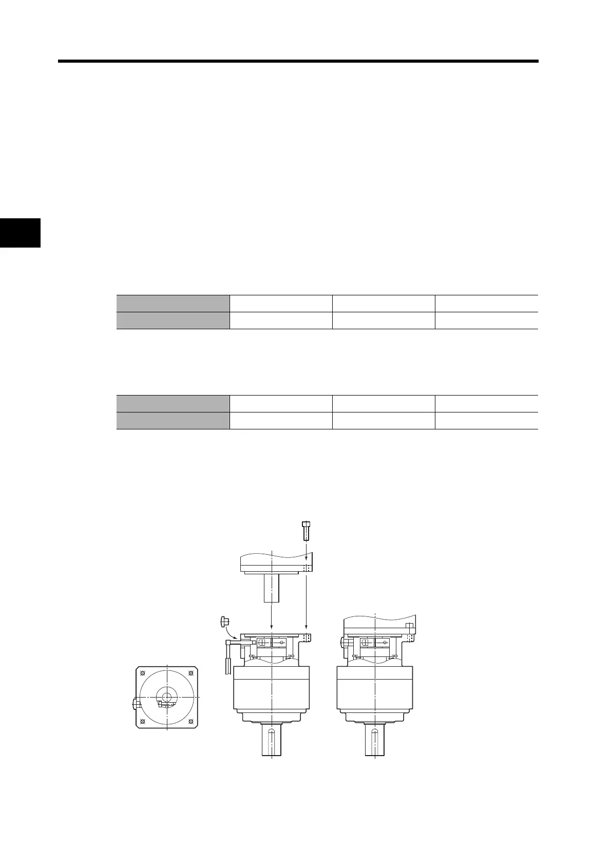
Use the following procedure to install the Decelerator on the Servomotor.
1. Turn the input joint and align the head of the bolt that secures the shaft with the
rubber cap.
Make sure the set bolts are loose.
2. Gently insert the Servomotor into the Decelerator.
As shown in the figures below, stand the Decelerator upright and slide the Servomotor shaft into the
input shaft joint while making sure it does not fall over. If the Decelerator cannot be stood upright,
tighten each bolt evenly little by little to ensure that the Servomotor is not inserted at a tilt.
3. Bolt together the Servomotor and the Decelerator flanges.
Bolt Tightening Torque
4. Tighten the input joint bolt.
Bolt Tightening Torque for Duralumin
Note Always use the torque given in the table above. The Servomotor may slip or other problems
may occur if the specified torque level is not satisfied.
5. Mount the supplied rubber cap to complete the installation procedure.
Allen head bolt size M4 M5 M6
Tightening torque (N·m) 3.0 5.8 9.8
Allen head bolt size M3 M4 M5
Tightening torque (N·m) 1.5 3.5 7.1

 Loading...


