4-26
4-2 Wiring
System Design
4
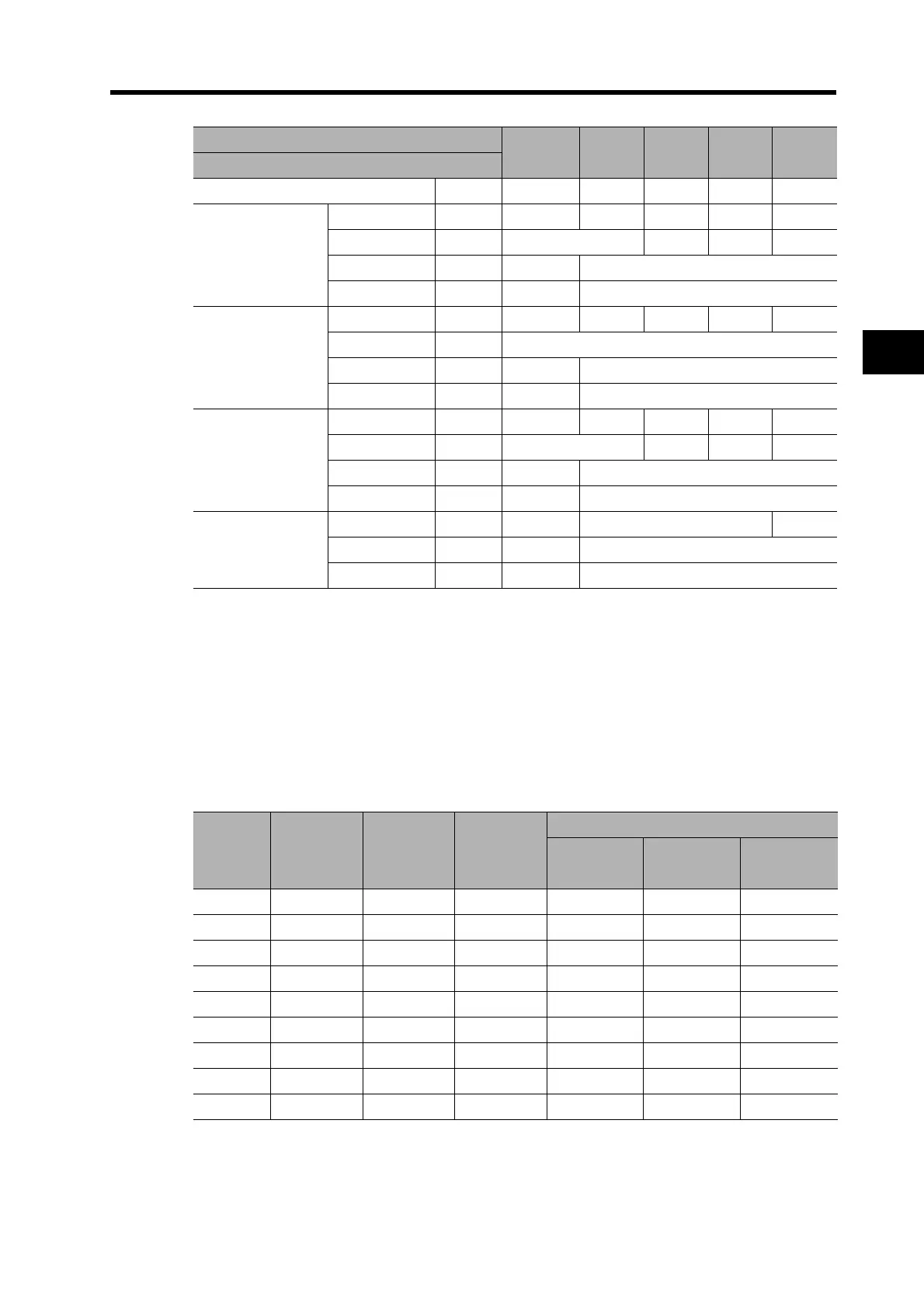
*1. The left value is for single-phase input power, and the right value is for three-phase input power.
*2. Use the same wire sizes for B1 and B2.
*3. Connect an OMRON Servomotor Power Cable to the Servomotor connection terminals.
Wire Sizes and Allowable Current (Reference)
The following table shows the allowable current when there are three power supply wires.
Use a current below these specified values.
600-V Heat-resistant Vinyl Wire (HIV)
Model (R88D-)
GN15H-
ML2
GN20H-
ML2
GN30H-
ML2
GN50H-
ML2
GN75H-
ML2
Item Unit
Power supply capacity kVA 2.3 3.3 4.5 7.5 11
Main circuit power
supply input
(L1 and L3, or
L1, L2, and L3)
*1
Rated current A 11.0/8.0
*1
10.2 15.2 23.7 35.0
Wire size --- AWG14 AWG12 AWG10 AWG8
Screw size --- --- M5
Torque Nm --- 2.0
Control circuit
power supply input
(L1C and L2C)
Rated current A 0.07 0.1 0.12 0.12 0.14
Wire size --- AWG18
Screw size --- --- M5
Torque Nm --- 2.0
Servomotor
connection
terminals
(U, V, W, and GR)
*2
Rated current A 9.4 13.4 18.6 33.0 47.0
Wire size --- AWG14 AWG12 AWG8 AWG6
Screw size --- --- M5
Torque Nm --- 2.0
Frame ground
(GR)
Wire size --- AWG14 AWG12 AWG8
Screw size --- M4 M5
Torque Nm 1.2 2.0
AWG size
Nominal
cross-sec-
tional area
(mm
2
)
Configura-
tion
(wires/mm
2
)
Conductive
resistance
(/km)
Allowable current (A) for ambient temperature
30C 40C 50C
20 0.5 19/0.18 39.5 6.6 5.6 4.5
--- 0.75 30/0.18 26.0 8.8 7.0 5.5
18 0.9 37/0.18 24.4 9.0 7.7 6.0
16 1.25 50/0.18 15.6 12.0 11.0 8.5
14 2.0 7/0.6 9.53 23 20 16
12 3.5 7/0.8 5.41 33 29 24
10 5.5 7/1.0 3.47 43 38 31
88.0 7/1.2 2.41 55 49 40
6 14.0 7/1.6 1.35 79 70 57

 Loading...


