9-4
9-1 Parameter Tables
Appendix
9
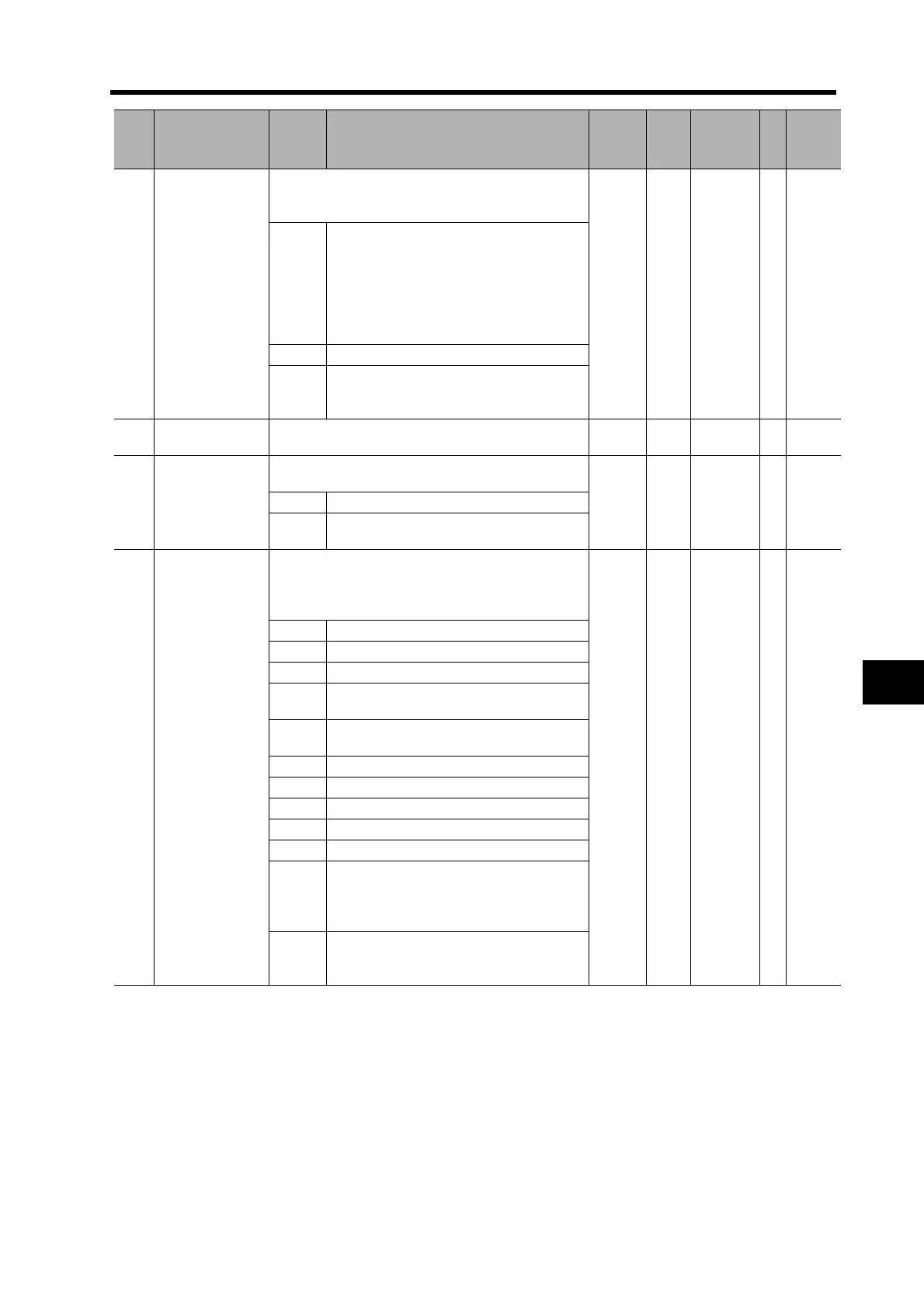
004
Drive Prohibit
Input Selection
Selects the function for the Forward and Reverse
Drive Prohibit Inputs (CN1 POT: pin 19, NOT: pin
20).
0 --- 0 to 2 C
0
Decelerates and stops according to the
sequence set in the Stop Selection for
Drive Prohibition Input (Pn066) when both
POT and NOT inputs are enabled.
When both POT and NOT inputs are
OPEN, the Drive Prohibit Input Error
(alarm code 38) will occur.
1 Both POT and NOT inputs disabled.
2
When either POT or NOT input becomes
OPEN, the Drive Prohibit Input Error
(alarm code 38) will occur.
005
Communications
Control
Controls errors and warnings for
MECHATROLINK-II communications.
0 --- 0 to 3955 C
006
Power ON
Address Display
Duration Setting
Sets the duration to display the node address when
the control power is turned ON.
30 ms 0 to 1000 C0 to 6 600ms
7 to
1000
set value
100 ms
007
Speed Monitor
(SP) Selection
Selects the output to the Analog Speed Monitor (SP
on the front panel).
Forward rotation is always positive (+), and reverse
rotation is always negative ().
3 --- 0 to 11 A ---
0 Actual Servomotor speed: 47 r/min/6 V
1 Actual Servomotor speed: 188 r/min/6 V
2 Actual Servomotor speed: 750 r/min/6 V
3
Actual Servomotor speed: 3000 r/min/
6 V
4
Actual Servomotor speed: 12000 r/min/
6 V
5 Command speed: 47 r/min/6 V
6 Command speed: 188 r/min/6 V
7 Command speed: 750 r/min/6 V
8 Command speed: 3000 r/min/6 V
9 Command speed: 12000 r/min/6 V
10
Outputs the Issuance Completion Status
(DEN).
0 V: Issuing
5 V: Issuance complete
11
Outputs the Gain Selection Status.
0 V: Gain 2
5 V: Gain 1
Pn
No.
Parameter name Setting Explanation
Default
Setting
Unit
Setting
Range
Attribute
Set
value

 Loading...


