2-41
2-2 External and Mounting Hole Dimensions
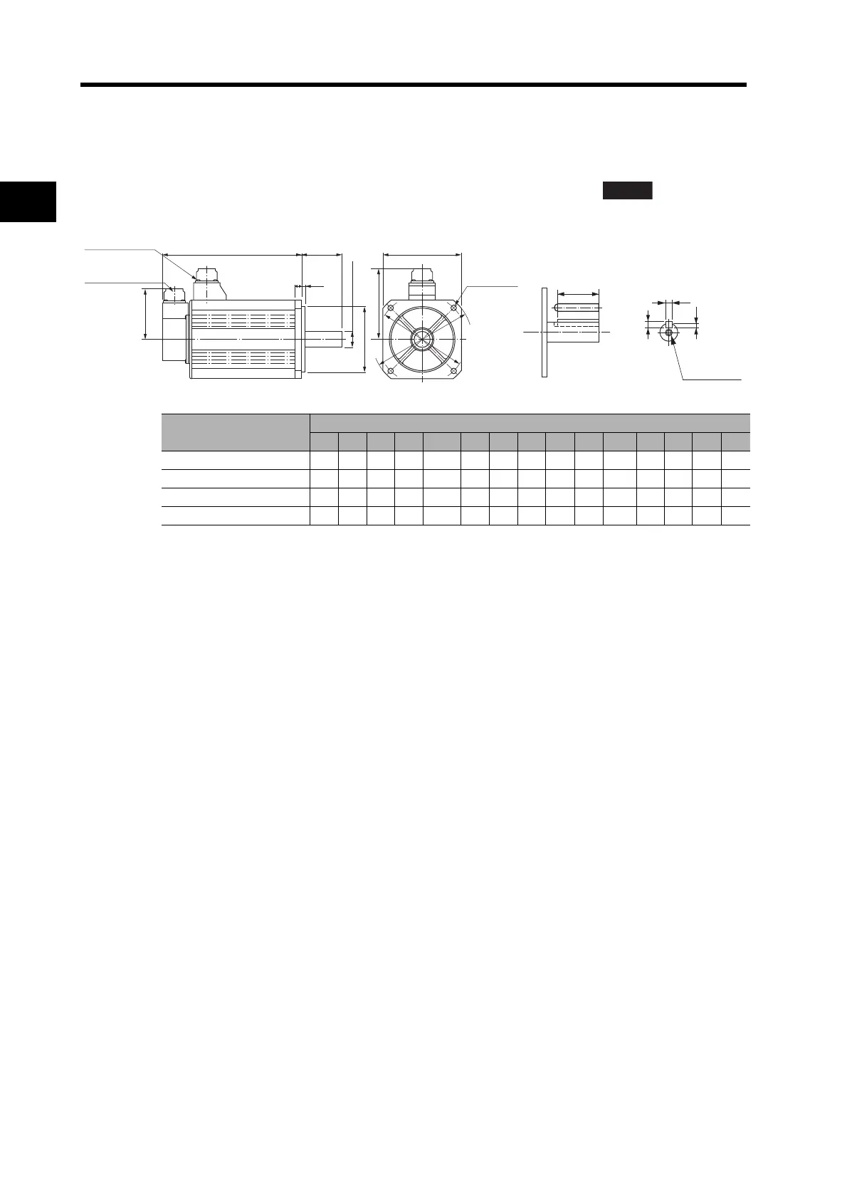
2
Standard Models and Dimensions
2,000-r/min Servomotors
4 kW/5 kW
R88M-G4K020T(-S2)/-G5K020T(-S2)/-G4K020T-B(S2)/-G5K020T-B(S2)
Note The standard models have a straight shaft. Models with a key and tap are indicated with
"S2" at the end of the model number.
Model
Dimensions (mm)
LL LR S D1 D2 C D3 KL1 Z QK b h t1 M L
R88M-G4K020 242 65 28 165 130 150 190 128 11 51 8h9 7 4 M8 20
R88M-G5K020 225 70 35 200 114.3 176 233 143 13.5 50 10h9 8 5 M12 25
R88M-G4K020-B 267 65 28 165 130 150 190 128 11 51 8h9 7 4 M8 20
R88M-G5K020-B 250 70 35 200 114.3 176 233 143 13.5 50 10h9 8 5 M12 25
ABS
LL LR
18
3.2
KL1
84
C × C
D1 dia.
D2 dia., h: 7
S dia., h: 6
D3 dia.
Four, Z dia.
Encoder
connector
Servomotor/brake
connector
QK
t1
h
b
M (depth: L)
(Dimensions of shaft end
with key and tap)

 Loading...


