2-42
2-2 External and Mounting Hole Dimensions
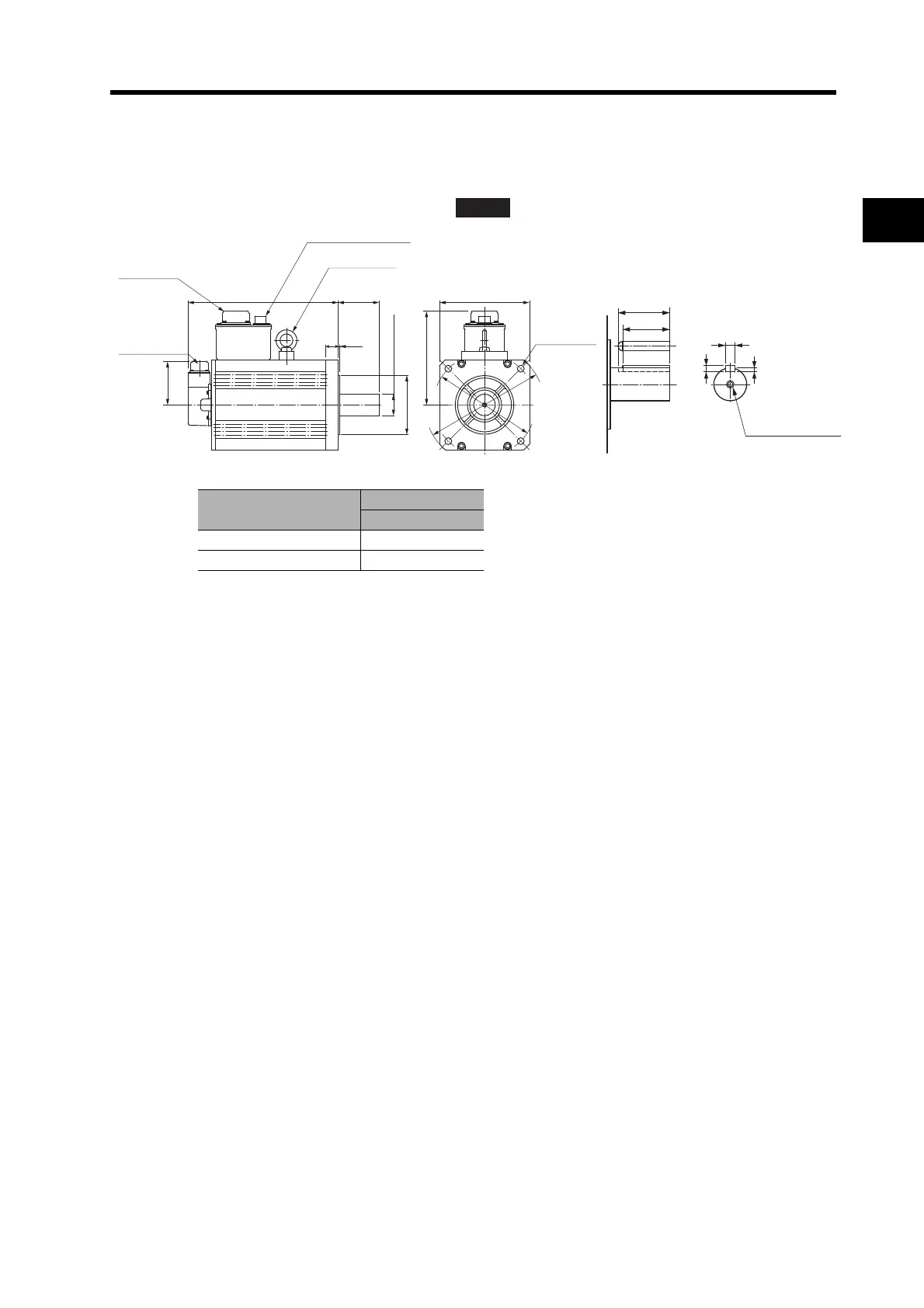
2
Standard Models and Dimensions
1,500-r/min Servomotors
7.5 kW
R88M-G7K515T(-S2)/-G7K515T-B(S2)
Note The standard models have a straight shaft. Models with a key and tap are indicated with
"S2" at the end of the model number.
Model
Dimensions (mm)
LL
R88M-G7K515 340.5
R88M-G7K515-B 380.5
ABS
90
96
M16 (depth:32)
12, h: 9
8
5
(Dimensions of shaft end
with key and tap)
Eye-bolt
Nominal diameter: 10
Brake connector
LL 113
24
3.2
183
84
176 × 176
Four, 13.5 dia.
200 dia.
114.3 dia., h: 7
42 dia., h: 6
233 dia.
Motor
connector
Encoder
connector

 Loading...


