2-50
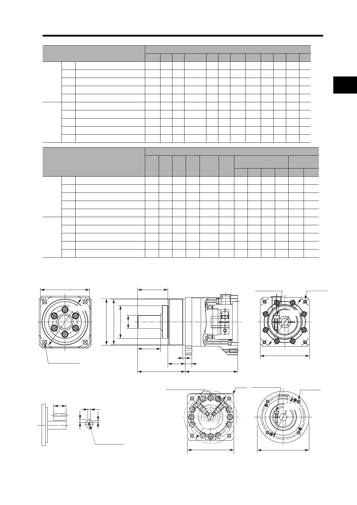
2-2 External and Mounting Hole Dimensions
2
Standard Models and Dimensions
*1. This is the set bolt.
Outline Drawings
Model
Dimensions (mm)
LM LR C1 C2 D1 D2 D3 D4 D5 E F1 F2
400 W
1/5 R88G-HPG14A05400B 64.0 58 60 6060 70 70 56.0 55.5 40 37 2.5 21
1/11 R88G-HPG20A11400B 71.0 80 90 89 dia. 105 70 85.0 84.0 59 53 7.5 27
1/21 R88G-HPG20A21400B 71.0 80 90 89 dia. 105 70 85.0 84.0 59 53 7.5 27
1/33 R88G-HPG32A33400B 104.0 133 120 122 dia. 135 70 115.0 114.0 84 98 12.5 35
1/45 R88G-HPG32A45400B 104.0 133 120 122 dia. 135 70 115.0 114.0 84 98 12.5 35
750 W
1/5 R88G-HPG20A05750B 78.0 80 90 8080 105 90 85.0 84.0 59 53 7.5 27
1/11 R88G-HPG20A11750B 78.0 80 90 8080 105 90 85.0 84.0 59 53 7.5 27
1/21 R88G-HPG32A21750B 104.0 133 120 122 dia. 135 90 115.0 114.0 84 98 12.5 35
1/33 R88G-HPG32A33750B 104.0 133 120 122 dia. 135 90 115.0 114.0 84 98 12.5 35
1/45 R88G-HPG32A45750B 104.0 133 120 122 dia. 135 90 115.0 114.0 84 98 12.5 35
Model
Dimensions (mm)
G S T Z1 Z2 AT
*1
Key dimensions
Tap
dimensions
QK b h t1 M L
400 W
1/5 R88G-HPG14A05400B 8 16 28 5.5 M410 M4 25 5 5 3 M4 8
1/11 R88G-HPG20A11400B 10 25 42 9.0 M410 M4 36 8 7 4.0 M6 12
1/21 R88G-HPG20A21400B 10 25 42 9.0 M410 M4 36 8 7 4.0 M6 12
1/33 R88G-HPG32A33400B 13 40 82 11.0 M410 M4 70 12 8 5.0 M10 20
1/45 R88G-HPG32A45400B 13 40 82 11.0 M410 M4 70 12 8 5.0 M10 20
750 W
1/5 R88G-HPG20A05750B 10 25 42 9.0 M512 M4 36 8 7 4.0 M6 12
1/11 R88G-HPG20A11750B 10 25 42 9.0 M512 M4 36 8 7 4.0 M6 12
1/21 R88G-HPG32A21750B 13 40 82 11.0 M512 M6 70 12 8 5.0 M10 20
1/33 R88G-HPG32A33750B 13 40 82 11.0 M512 M6 70 12 8 5.0 M10 20
1/45 R88G-HPG32A45750B 13 40 82 11.0 M512 M6 70 12 8 5.0 M10 20
C1 × C1
Four, Z1 dia.
D3 dia., h: 7
D5 dia.
D4 dia.
C2 × C2
Four, Z2Set bolt (AT)
C2 dia.
Four, Z2
Set bolt (AT)
E
T
F1
F2
LR
G
LM
D1 dia.
S dia., h: 7
D2 dia.
D2 dia.
For the R88G-HPG11B Series, two set bolts
are positioned at 90° from each other.
Set bolts (AT)
4-Z2
C2 dia.
D2 dia.
QK
Key and Tap Dimensions
b
h
t1
M (depth: L)

 Loading...


