Do you have a question about the Oracle SPARC T5-8 and is the answer not in the manual?
Processor | SPARC T5 |
---|---|
Number of Sockets | 8 |
Cores per Processor | 16 |
Threads per Core | 8 |
Total Cores | 128 |
Processor Speed | 3.6 GHz |
Memory Capacity | 4 TB |
Memory Type | DDR3 |
Network Ports | 4 x 10 GbE |
L2 Cache | 128 KB per core |
Operating System | Oracle Solaris |
Storage Options | SAS, SATA, SSD |
Networking | Integrated 10 Gigabit Ethernet |
Power Supply | Redundant Power Supply |
Form Factor | Rackmount |
Describes how to troubleshoot and maintain the server.
Technicians, system administrators, and authorized service providers.
Advanced experience troubleshooting and replacing hardware.
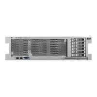
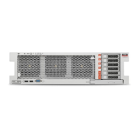
Identifies front panel components and their features.
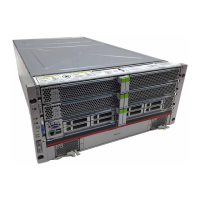
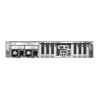
Identifies rear panel components and their features.
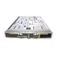
Shows the location of DIMMs within the processor modules.
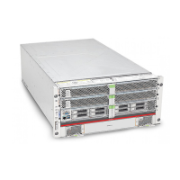
Illustrates internal components within the main module.
Lists the types of storage devices supported by the server.
Shows the locations of the fan modules in the server.
Details the ports available on the rear I/O module.
Identifies components within the chassis subassembly.
Lists server components and their service tasks.
Explains diagnostic processes and tools for troubleshooting faults.
Guides on understanding server LED indicators for fault diagnosis.
Details how to configure Power-On Self-Test as a diagnostic tool.
Describes the Predictive Self-Healing (PSH) feature for fault management.
Explains how to view logs for troubleshooting.
Lists safety precautions for server setup and handling.
Lists the necessary tools for performing service operations.
Describes different types of filler panels and modules in the server.
Provides methods to locate the server's serial number.
Guides on how to locate the server using the Locator LED.
Details different methods for removing power from the server.
Steps to protect components from electrostatic discharge.
Steps for upgrading the server to a fully-populated configuration.
Explains the LEDs on the processor modules.
How to identify a faulty processor module using LEDs.
Procedure for removing processor modules or filler modules.
Procedure for installing processor modules or filler modules.
Steps to verify a replaced processor module.
Topics related to installing, upgrading, or replacing DIMMs.
Guidelines for using and installing DIMMs.
Explains DIMM addresses and shows the layout.
How to determine a faulty DIMM using the FMA command.
How to identify a faulty DIMM using LEDs.
Procedure for removing DIMMs or filler panels.
Procedure for installing a new DIMM.
Steps to verify a successfully installed DIMM.
Explains the LEDs on the hard drives.
How to identify a faulty hard drive using LEDs.
Procedure for removing a hard drive.
Procedure for installing a new hard drive.
Steps to verify a successfully installed hard drive.
Explains the LEDs on the main module.
How to identify a faulty main module using LEDs.
Procedure for removing the main module.
Procedure for installing a new main module.
Steps to verify a successfully installed main module.
Procedure for removing a storage backplane.
Procedure for installing a new storage backplane.
Steps to verify a successfully installed storage backplane.
How to identify a faulty service processor card.
Procedure for removing the service processor card.
Procedure for installing a new service processor card.
Steps to verify a successfully installed service processor card.
Procedure for removing the system configuration PROM.
Procedure for installing a new system configuration PROM.
Steps to verify a successfully installed PROM.
Procedure for removing the system battery.
Procedure for installing a new battery.
Steps to verify a successfully installed battery.
Procedure for removing the front I/O assembly.
Procedure for installing a new front I/O assembly.
Steps to verify a successfully installed assembly.
Explains the LEDs on the power supplies.
How to identify a faulty power supply.
Procedure for removing a power supply.
Procedure for installing a new power supply.
Steps to verify a successfully installed power supply.
Explains the LED on the fan modules.
How to identify a faulty fan module.
Procedure for removing a fan module.
Procedure for installing a new fan module.
Steps to verify a successfully installed fan module.
Explains PCIe root complex and fabric relationships.
Guidelines for optimal load balancing when installing PCIe cards.
Details the LEDs and controls on PCIe carriers.
How to identify a faulty PCIe card using LEDs.
Procedure for removing a PCIe card carrier.
Procedure for removing a PCIe card from its carrier.
Procedure for removing a PCIe card carrier extension.
Procedure for installing a PCIe card carrier extension.
Procedure for installing a PCIe card into its carrier.
Procedure for installing a PCIe card carrier.
Steps to verify a successfully installed PCIe card.
How to determine if the rear I/O module is faulty.
Procedure for removing the rear I/O module.
Procedure for installing a new rear I/O module.
Steps to verify a successfully installed module.
How to determine if the rear chassis subassembly is faulty.
Procedure for removing the rear chassis subassembly.
Procedure for installing a new rear chassis subassembly.
Steps to verify the rear chassis subassembly installation.
Steps for connecting power cords to the server.
How to power on the server using Oracle ILOM.
How to power on the server using the front panel button.