Associated Equipment 5-5
AC30 series Variable Speed Inverter
Dynamic Braking Resistors
We can supply suitable braking resistors, found on the following pages. Alternatively, you can use the calculation on page 5-7 to help you
select alternative resistors.
We recommend using a thermal overload switch to protect the braking circuit. Refer to page 5-6.
The inverter must be fitted with external braking resistors if braking is required.
The power stack must be fitted with external braking resistors, or used with an AFE or regenerative DC supply unit, if
braking is required.
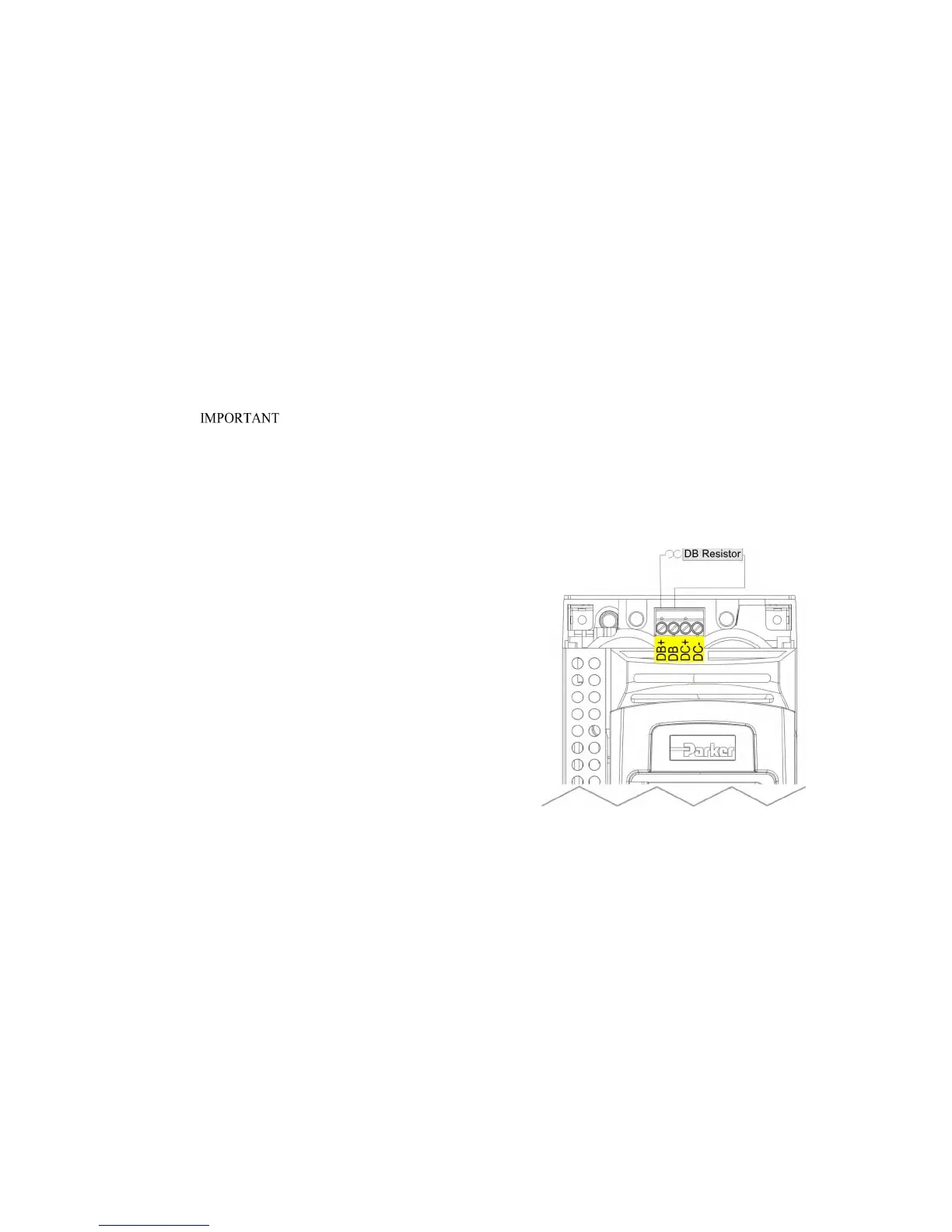
WIRING DETAILS
WARNING
Do not apply external voltage sources (mains
supply or otherwise) to either of the braking
terminals: DB+, DB. This can lead to damage to the
inverter and installation, and risk to personnel.