F-23 Technical Specifications
AC30 series Variable Speed Drive
SYSTEM AUXILIARY 24V INPUT – AC30D ONLY
+24V AUX input (X30/05), 0V AUX input (X30/06)
24V +10%
This is the system auxiliary power input. It is used to power the isolated encoder power supply output (X31/07-08 and
X32/07-08) and the encoder transmit output (X33/01-06).
It will also keep the entire control module (digital I/O, analog I/O, options and GKP) powered when the main stack
power is off.
A common non-earthed SELV supply can be used to power more than one control module, by bussing the supply to
the +24V system aux. input terminal (X30/05) and to the 0V system aux. input terminal (X30/06), on each drive.
1.5A minimum supply required, per control module.
2.0A peak current on power-up, per control module.
The supply to these inputs should be suitably externally fused at 2A, at each individual drive, to protect the control
module and supply wiring.
DIGITAL INPUTS – AC30D ONLY
DIN1 (X30/01) – DIN3 (X30/03), DIN0V (X30/04)
Conforming to EN61131-2
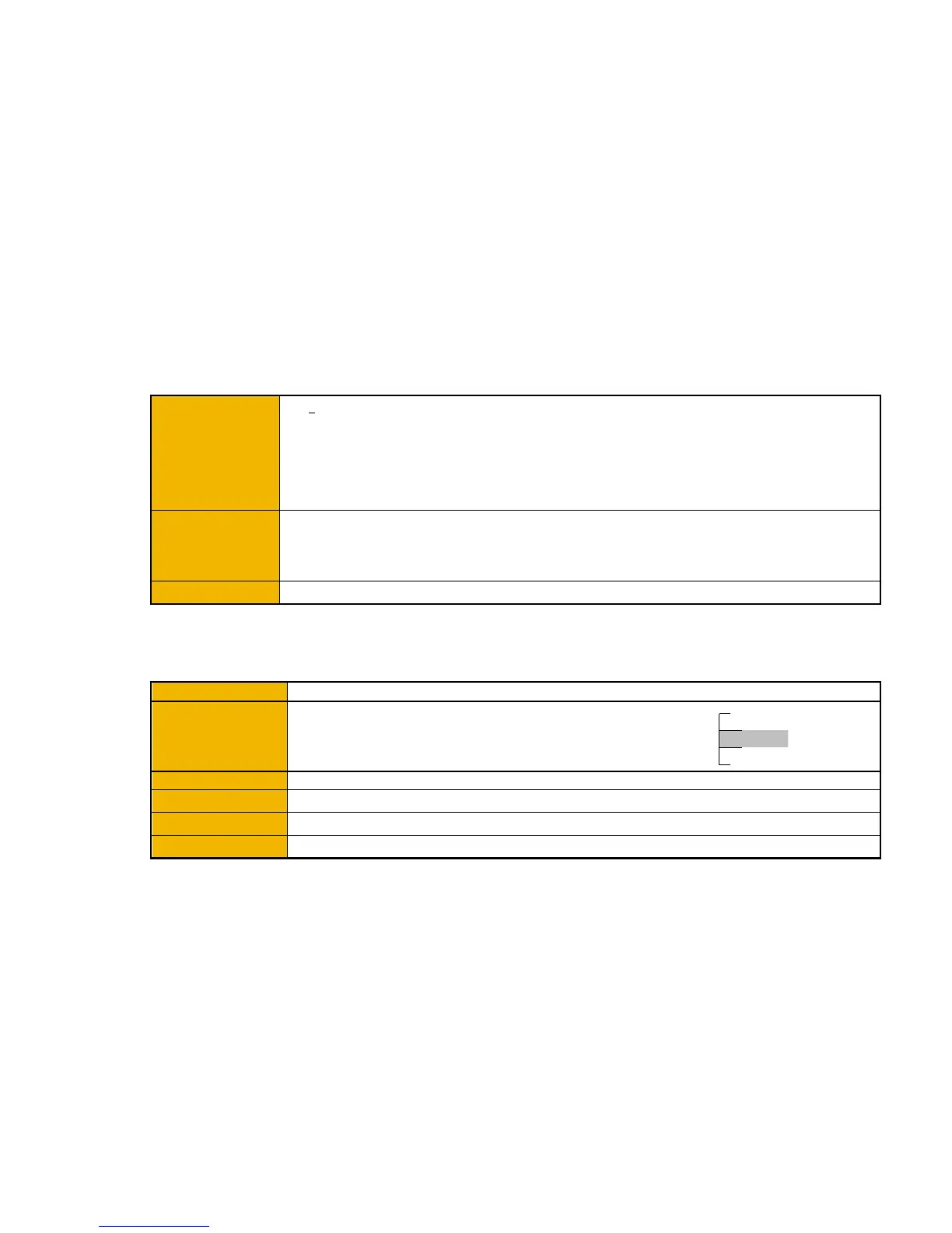
DIN1, DIN2, DIN3:
0-5V dc = OFF, 15-24V dc = ON
(absolute maximum input voltage ±30V dc)
undefined state
15V
5V
0V
24V
ON
OFF

 Loading...


