EasyManuals Logo

Parker AC30 User Manual

Parker AC30
522 pages
To Next Page IconTo Next Page
To Previous Page IconTo Previous Page
Page #114 background imageLoading...
Page #114 background image
7-2 The Graphical Keypad
AC30 series Variable Speed Inverter
Overview
The top line of the display is used to show the inverter status
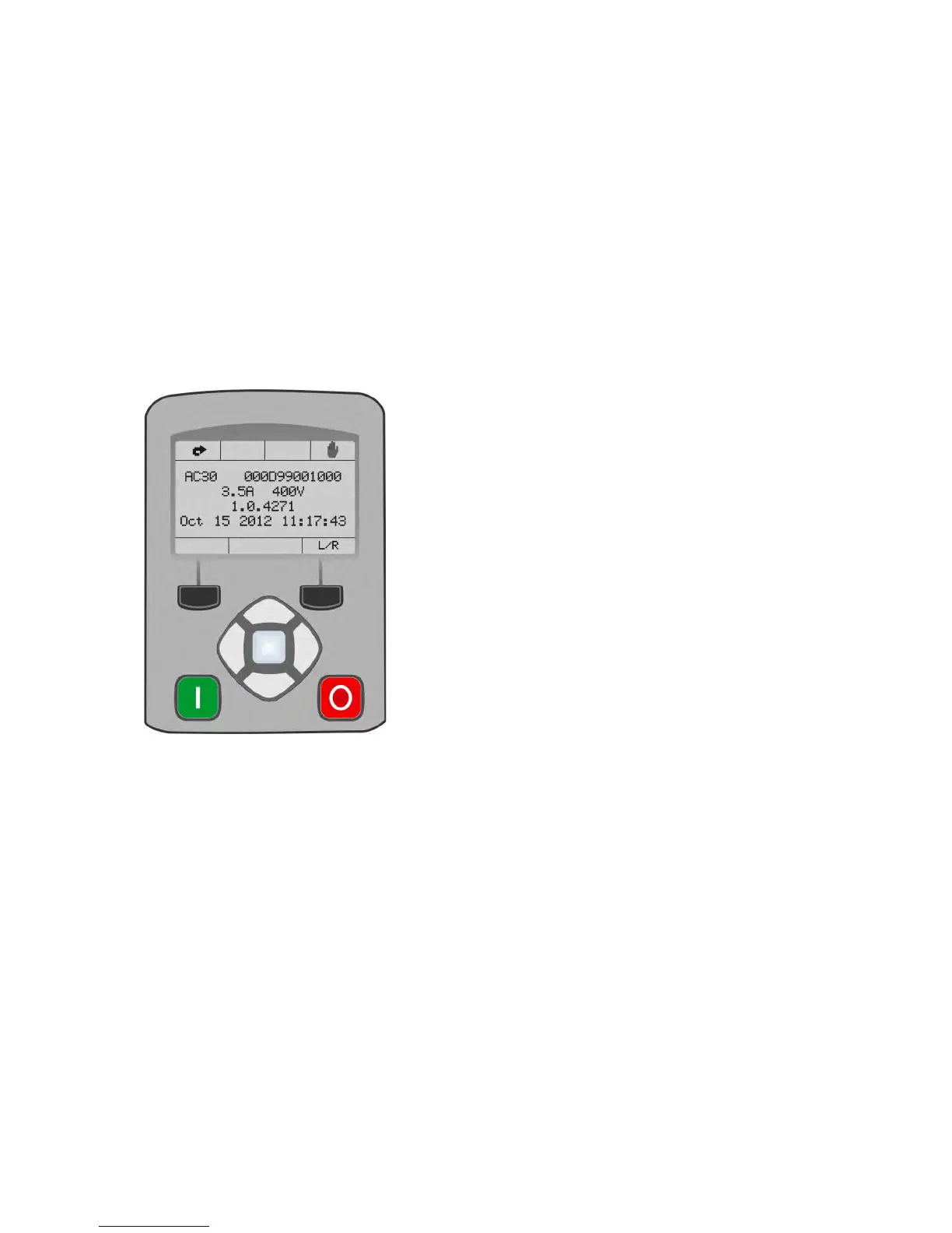
The central region of the display shows the selected parameters or navigation menu
The bottom line of the display indicates the action associated with the soft keys
The actions of the soft keys are context dependent
The central navigation and editing keys are referred to as UP, DOWN, LEFT, RIGHT and
OK
The Run, (green), and Stop, (red), keys are used to start and stop the motor when the
inverter is in local control mode.

Table of Contents

Other manuals for Parker AC30

Questions and Answers:

Question and Answer IconNeed help?

Do you have a question about the Parker AC30 and is the answer not in the manual?

Parker AC30 Specifications

General IconGeneral
Protection RatingIP20
SeriesAC30
TypeVariable Frequency Drive
Overload Capacity150% for 60 seconds
Cooling MethodFan Cooled
Communication ProtocolsCANopen
Power Range0.75 to 250 kW (1 to 350 hp)
Switching Frequency2kHz to 16kHz
SafetySafe Torque Off (STO)
Output CurrentModel Dependent
Power Rating0.75 to 250 kW (1 to 350 hp)
Efficiency>97%
Protection FeaturesOvercurrent, overvoltage, undervoltage, short circuit, overheating
DimensionsModel Dependent
WeightModel Dependent
Operating Temperature-10°C to +40°C
Output Voltage0 to Input Voltage

Related product manuals