Chapter F - ADJUSTMENTS
Planmeca Compact i F-19
ELECTRICAL ADJUSTMENTS
Technical Manual
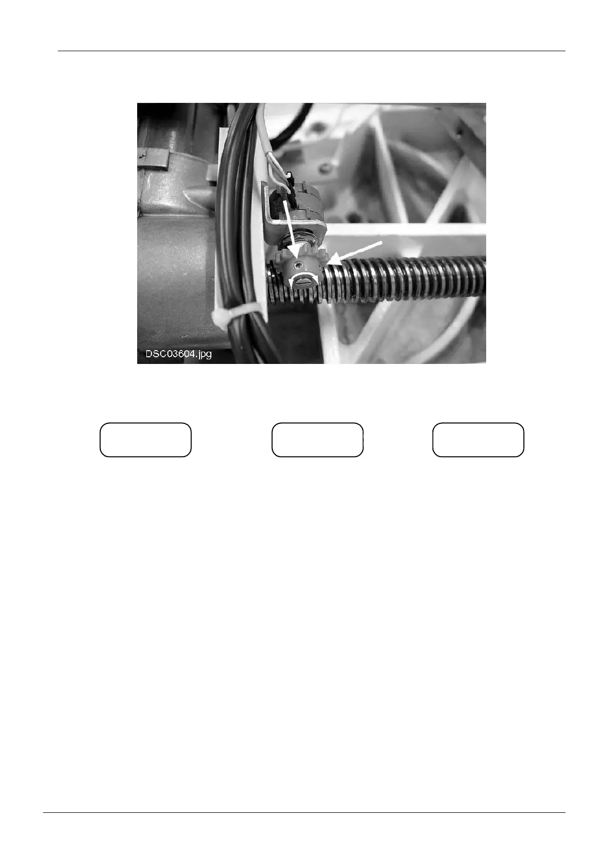
d) Loosen the two M3x6 DIN 916 screws at the side of the cog wheel of the sensor.
e) Rotate the axle of the sensor with a screwdriver until the two horizontal lines on the display
are in line.
f) Tighten the two M3x6 DIN 916 screws to secure the cog wheel into position.
g) Using the A key drive the backrest downwards and after the lowest position is reached
continue pressing the A key for approx. 2 seconds to drive the backrest to horizontal position.
Check that the spindle nut does not touch the cog wheel or potentiometer.
h) Drive the guiding nut past the calibration mark a couple of times to ensure that the sensor is
now calibrated correctly (the horizontal lines are aligned).
i) Exit service mode.
b –_ b –b – –
The sensor presumes the back-
rest to be at a too low position.
Rotate the sensor axle counter
clockwise (seen from the axle).
The sensor presumes the back-
rest to be at a too high position.
Rotate the sensor axle clockwise
(seen from the axle).
The backrest position sen-
sor is calibrated correctly.
–