4.25
ELECTRONIC FUEL INJECTION
4
9924096 - 2013 RANGER RZR XP 900 / RZR XP 4 900 Service Manual
© Copyright 2012 Polaris Sales Inc.
13. Unscrew the throttle cable adjuster and jam nut from
the throttle body. Remove the throttle body from the
vehicle.
14. Reverse the previous steps to reinstall the throttle
body.
15. Upon installation of the throttle cable, refer to Chapter
2 “Throttle Freeplay Adjustment”. Torque the throttle
body cover screws to specification.
16. Upon installation of the fuel rail and injectors, lightly
lubricate injector O-rings to aid installation. Torque the
fuel rail mounting screws to specification.
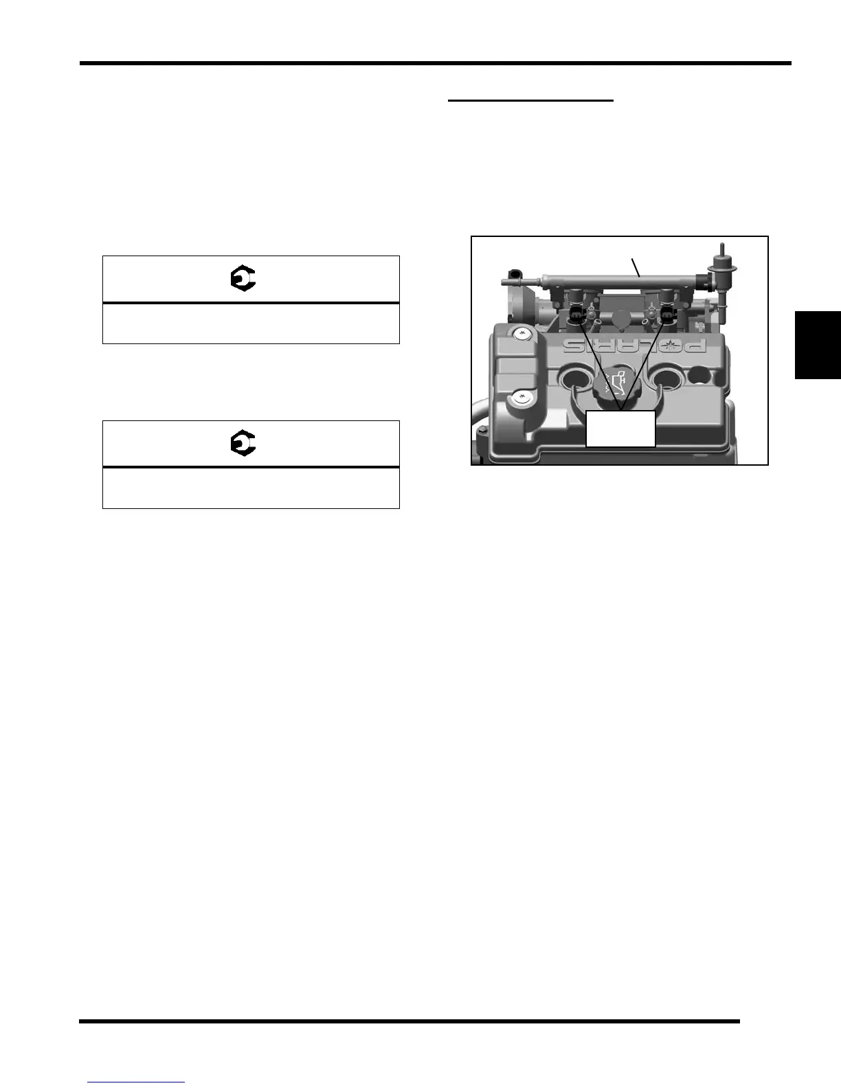
FUEL INJECTORS
Operation Overview
The fuel injectors are mounted into the dual throttle body
assembly, with the fuel rail retaining them from the top end.
O-rings on both ends of the injector prevent external fuel
leaks and also insulate the injectors from heat and
vibration.
When the key switch is on, the fuel rail is pressurized, and
the EFI relay provides voltage to the injectors. During
engine operation, the ECU completes the ground circuit,
energizing the injectors. The valve needle in each injector
is opened electromagnetically, and the pressure in the fuel
rail forces fuel down through the inside. The “director
plate” at the tip of the injector contains a series of
calibrated openings which directs the fuel into the intake
port in a cone-shaped spray pattern.
The amount of fuel injected is controlled by the ECU and
determined by the length of time the valve needle is held
open, also referred to as the “injection duration” or “pulse
width”. It may vary in length depending on the speed and
load requirements of the engine.
The ECU gathers fuel injection timing information from the
Crankshaft Position Sensor (CPS) and the Manifold Air
Quality Sensor (MAQS) to allow for sequential fuel
injection.
Throttle Body Cover Screws:
18 in-lbs (2 Nm)
Fuel Rail Mounting Screws:
44 in-lbs (5 Nm)

 Loading...