10.14
ELECTRICAL
9924096 - 2013 RANGER RZR XP 900 / RZR XP 4 900 Service Manual
© Copyright 2012 Polaris Sales Inc.
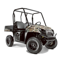
Turn Signal Switch (INT’L)
1. Disconnect the Turn Signal switch harness by
depressing the connector locks and pulling on the
connector. Do not pull on the wiring.
2. Test between the 5 sets of outputs (HI BEAM / LO
BEAM / L-TURN / R-TURN / HORN). If any of the tests
fail, replace the switch assembly.
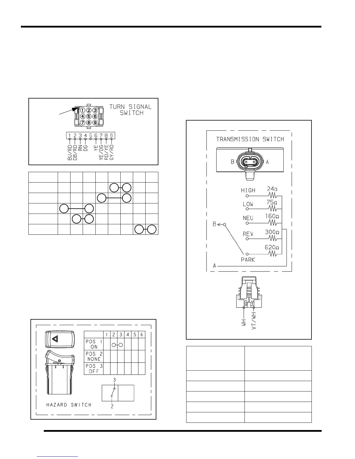
Hazard Switch (INT’L)
1. Disconnect wires or harness from the Hazard switch.
2. Test between the outputs (ON / NONE / OFF). If any
of the tests fail, replace the switch assembly.
• Move switch to ON. There should be continuity
between switch pins 2 and 3.
• Move switch to NONE / OFF. There should be no
continuity between switch pins.
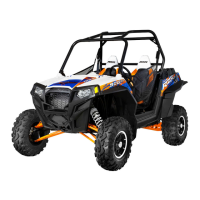
Transmission (Gear Position) Switch
1. The transmission (gear position) switch is located on
the RH side of the transmission and can be accessed
through the RH wheel well area.
2. Disconnect the transmission switch harness by lifting
the connector lock and pulling on the connector. Do
not pull on the wiring.
3. Test the transmission switch continuity readings for
each gear position and compare to the specification
table below.
1 2 3 4 6 7 8 9
HI BEAM
LO BEAM
L - TURN
R - TURN
HORN
Gear Position
Resistance Value
when measured at
switch terminals A and B
HIGH 24
LOW 75
NEU 160
REV 300
PARK 620
 Loading...