6.12
CLUTCHING (PVT)
9924096 - 2013 RANGER RZR XP 900 / RZR XP 4 900 Service Manual
© Copyright 2012 Polaris Sales Inc.
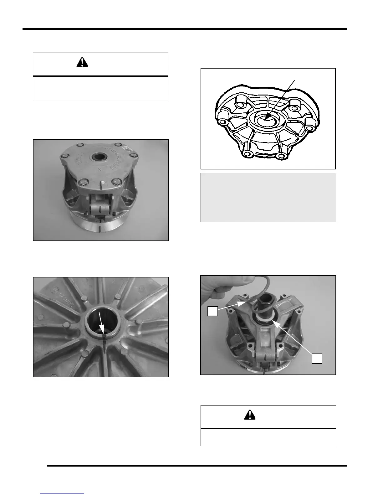
Drive Clutch Disassembly / Inspection
1. Using a permanent marker, mark the cover, spider,
moveable and stationary sheaves for reference, as
the cast in X's may not have been in alignment before
disassembly.
2. Mark the stationary sheave and clutch shaft to verify
the shaft has not rotated in the sheave after tightening
the spider during clutch assembly.
IMPORTANT: Upon reassembly, if the reference
marks created in step 2 are not in alignment, the
clutch will not be in balance and the assembly MUST
be replaced.
3. Remove cover bolts evenly in a cross pattern and
remove cover plate.
4. Inspect cover bushing (A). The outer cover bushing is
manufactured with a Teflon™ coating. Wear is
determined by the amount of Teflon™ remaining on
the bushing.
5. Inspect area on shaft where bushing rides for wear,
galling, nicks, or scratches. Replace clutch assembly
if worn or damaged.
6. Remove and inspect the clutch spring (B). Refer to
“Drive Clutch Spring Inspection”.
7. Remove and inspect limiter spacer (C). Replace if
necessary.
The clutch assembly is a precisely balanced
unit. Never replace parts with used parts from
another clutch assembly!
Cover Bushing Inspection:
Replace the cover bushing if more
brass than Teflon™ is visible on
the bushing. Refer to bushing
replacement in this chapter.
DO NOT reassemble the drive clutch without the
limiter spacer. Belt life will be greatly reduced.
 Loading...