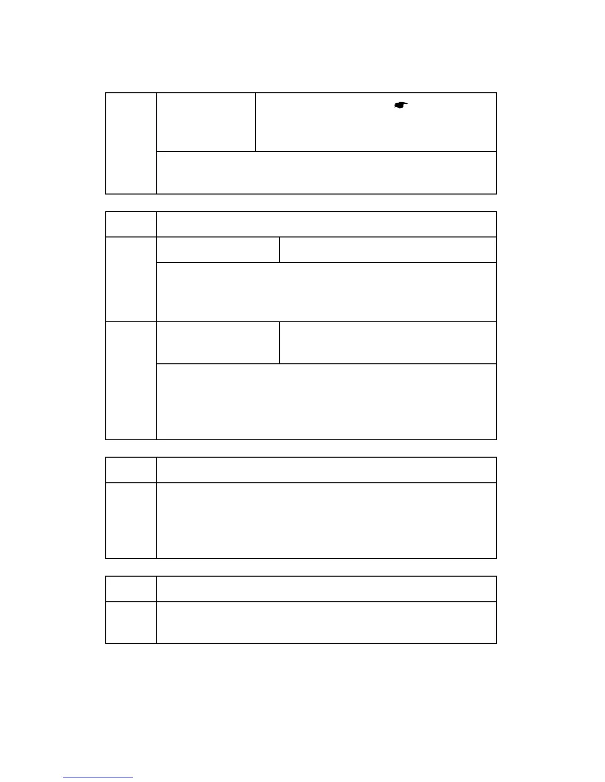
SP Mode Tables
D096 4-6 SM Appendix
2101 4
Right side
[0.0 to 9.0 / 2.0 / 0.1 mm/step] (
Copy Adjustments
Printing/Scanning)
Specification: 2 +2.5/–1.5 mm
Adjusts the right edge erase margin. The rear right edge is this value plus 0.3
mm.
2201*
Development Bias Adjustment
2201 1
Printing
[–1500 to –200 / –650 / 1 V/step]
Adjusts the voltage applied to the development roller when printing. This can
be adjusted as a temporary measure if faint copies are being produced due
to an aging drum.
2201 2
ID sensor pattern
[–2 = LL (220 V) / -1 = L (260 V) / 0 = N (300 V) /
1 = H (340 V) / 2 = HH (380 V)]
Adjusts the voltage applied to the development roller when generating the ID
sensor pattern. The actual voltage applied is this setting plus the value of SP
2201 1. The setting affects ID sensor pattern density, which in turn affects the
toner supply.
2213*
Outputs after Near End
2213 1
[0 = 50 pages / 1 = 20 pages]
Sets the number of copy/print pages that can be made after toner near-end
has been detected. Reduce the number of pages if the user normally makes
copies with a high image ratio.
2214
Developer Initialization
2214 1
Initializes both the TD sensor toner supply target voltage and the TD sensor
gain value. Carry this out after replacing the developer or the TD sensor.