Saia-Burgess Controls AG
Manual Manual PCD 1 / PCD 2 Series │ Document 26 / 737 EN22 │ 2013-11-26
5
Input/output (I/O) modules
5-98
Combined analogue I/O modules with galvanic isolation
Function
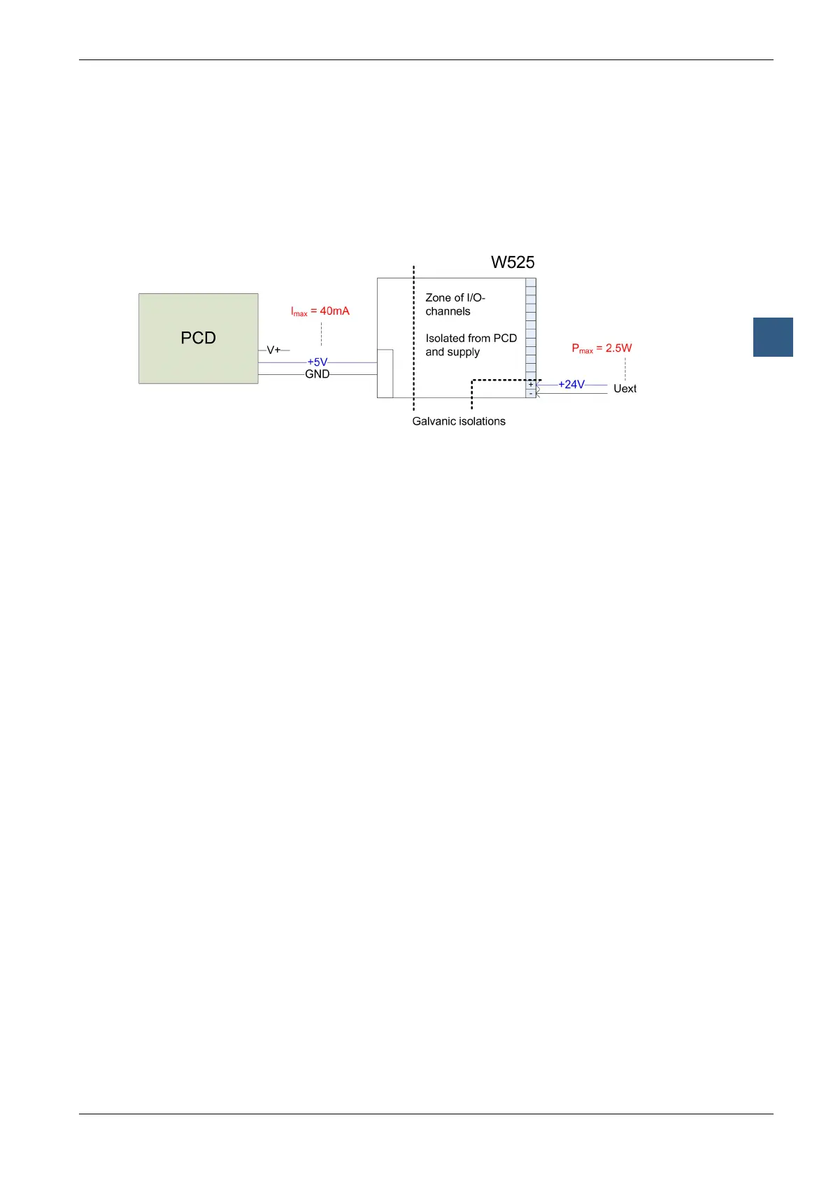
Power Supply
PCD2.W525 has to be supplied externally! This power supply is galvanically isolated
to both, the Saia PCD
®
and the I/Os of W525. Furthermore, the design allows using
the same power supply for the Saia PCD
®
and for W525 without loosing the galvanic
isolation. These schematics show the different zones of isolation:
Timing
● Inputs
○ Internally, W525 nishes acquiring every 2 ms a new value for every
input channel
○ This value is always ready to be read by the Saia PCD
®
.
○ Dependent on the Saia PCD
®
speed, the transmission time of a single
16-Bit scaled value (of a single input channel) takes typically 100 μs (on
a PCD2.M480) or 600μs (on a PCD2.M170)
● Outputs
○ Internally, W525 outputs the last received output value from Saia PCD
®
with a maximum delay of 2 ms.
○ Dependent on the Saia PCD
®
speed, the transmission time of a single
16-Bit scaled output value takes typically 100 μs (on a PCD2.M480) or
600 μs (on a PCD2.M170).
Filter
● Inputs
There are two factors, which have ltering effects to the acquired values:
○ The base hardware lter with a time constant of 2 ms. This lter attenu-
ates the input signal by 6 dB/decade at a cut-off frequency of 80 Hz.
○ The second inuence is caused by software and results in a delay of
the acquired value for 2 ms with a notch lter characteristics at 500 Hz if
no software based 50 Hz / 60 Hz lter is selected.
In case of use of a 50 Hz (60 Hz) lter, the notch lter frequency is 50 Hz
(60 Hz); the delay remains the mentioned 2ms.
● Outputs
There is only the hardware based lter with a time constant of 1 ms, which is
active
 Loading...


