Saia-Burgess Controls AG
Manual Manual PCD 1 / PCD 2 Series │ Document 26 / 737 EN22 │ 2013-11-26
5
Input/output (I/O) modules
5-97
Combined analogue I/O modules with galvanic isolation
Conguration
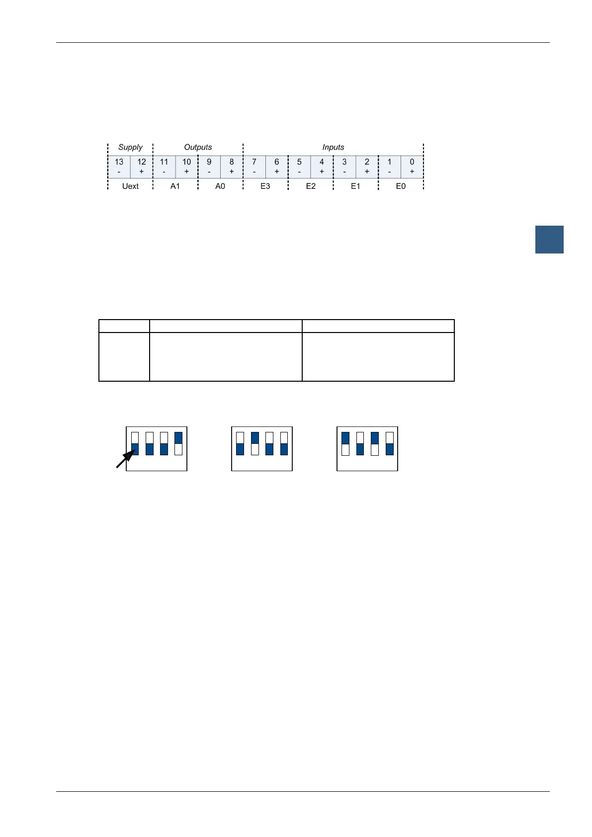
Module connections/LED
The connections of the module terminal are the following:
Description of the LED:
● Off: Module is not powered. U
ext
(24 V) is missing.
● On: Module is running without errors
● Blinking slow: Channel error (Over range/under range/short circuit/open load)
● Blinking fast: U
ext
is lower than specified (< 19 V)
How to congure the inputs
Each input channel is congured by a DIP-Switch with four switches. The function of
each switch is the following:
Switch nr. Off On
1
2
3
4
Differential Mode
Gain=1
Single Ended Mode
Current Shunt On
Supply for external Resistors On
Gain=0.25
According to this table, the conguration for the different modes of operation is as fol-
lows:
Voltage mode
0...10 V
Current mode
0...20 mA
4...20 mA
Temperature mode
Pt1000 (-50...400 ˚C)
Pt500 (-50...400 ˚C)
Ni1000 (-60...200 ˚C)
Resistor mode
1 2 3 4
On
Off
1 2 3 4
On
Off
1 2 3 4
On
Off
slider
How to congure the outputs
Since the outputs are congured by software (with the corresponding FBox or FB),
there is no need to congure the mode of operation of the outputs with any kind of
jumpers or DIP-Switches.