180 CHAPTER 5 Working with J-Link and J-Trace
J-Link / J-Trace (UM08001) ©
2004-2017 SEGGER Microcontroller GmbH & Co. KG
5.3 JTAG interface
By default, only one device is assumed to be in the JTAG scan chain. If you have mul-
tiple devices in the scan chain, you must properly configure it. To do so, you have to
specify the exact position of the CPU that should be addressed. Configuration of the scan
is done by the target application. A target application can be a debugger such as the
IAR C-SPY® debugger, ARM’s AXD using RDI, a flash programming application such
as SEGGER’s J-Flash, or any other application using J-Link / J-Trace. It is the applica-
tion’s responsibility to supply a way to configure the scan chain. Most applications
offer a dialog box for this purpose.
5.3.1 Multiple devices in the scan chain
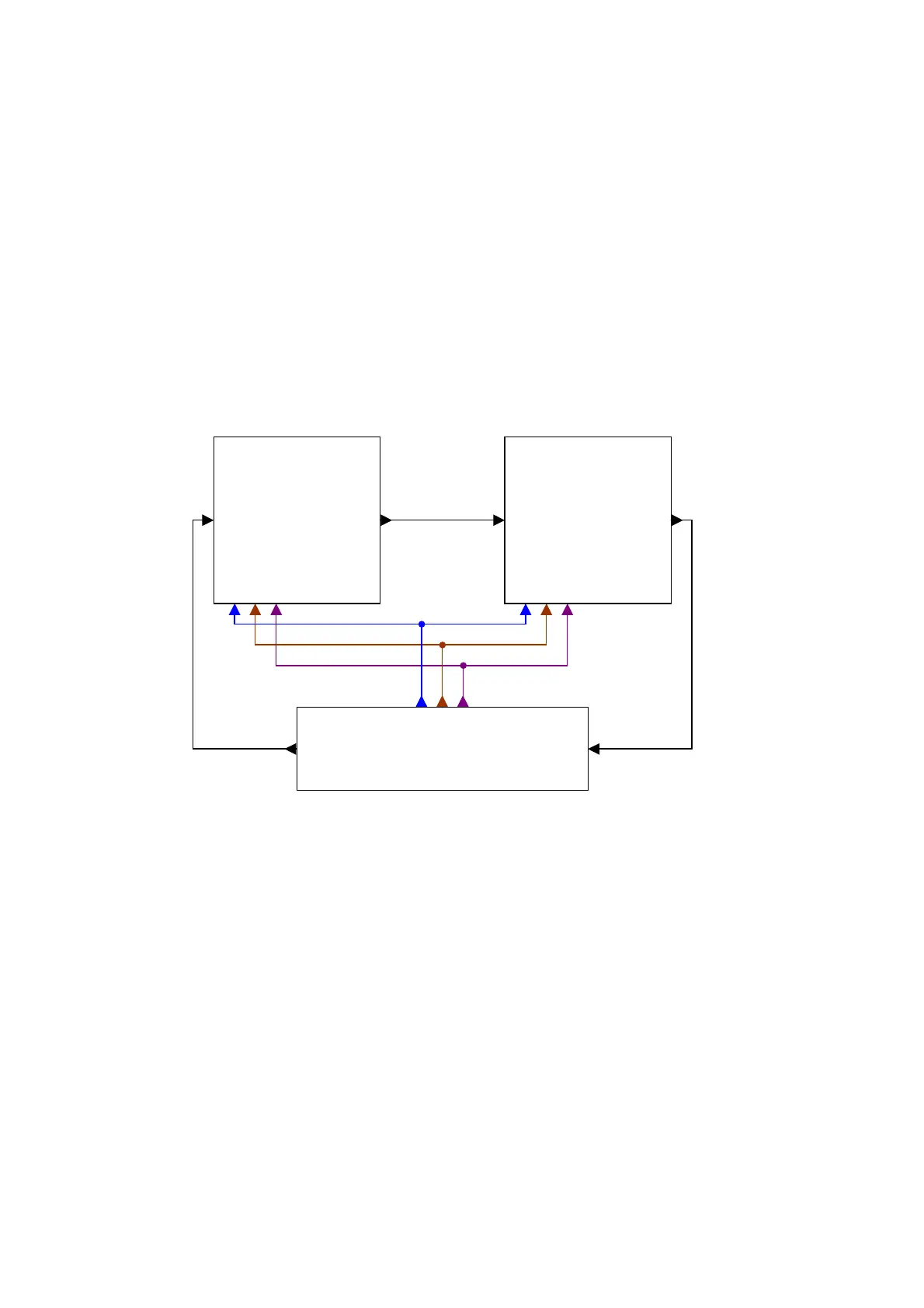
J-Link / J-Trace can handle multiple devices in the scan chain. This applies to hard-
ware where multiple chips are connected to the same JTAG connector. As can be seen
in the following figure, the TCK and TMS lines of all JTAG device are connected, while
the TDI and TDO lines form a bus.
Currently, up to 8 devices in the scan chain are supported. One or more of these
devices can be CPU cores; the other devices can be of any other type but need to
comply with the JTAG standard.
5.3.1.1 Configuration
The configuration of the scan chain depends on the application used. Read JTAG
interface on page 180 for further instructions and configuration examples.
5.3.2 Sample configuration dialog boxes
As explained before, it is the responsibility of the application to allow the user to con-
figure the scan chain. This is typically done in a dialog box; some sample dialog
boxes are shown below.
Device 1 Device 0
TDI TDITDO TDO
TDI
TDO
JTAG
TRST
TCK
TMS
TCK
TMS
TRST
TCK
TMS
TRST