J-Link / J-Trace (UM08001) © 2004-2017 SEGGER Microcontroller GmbH & Co. KG
437
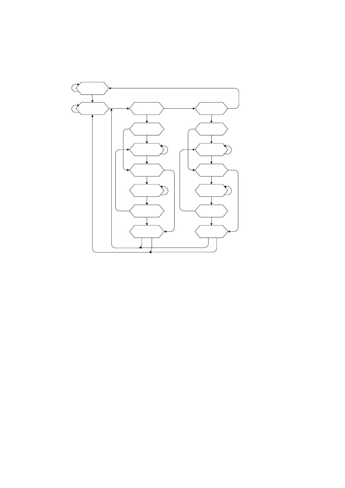
17.1.4 The TAP controller
The TAP controller is a synchronous finite state machine that responds to changes at
the TMS and TCK signals of the TAP and controls the sequence of operations of the
circuitry.
TAP controller state diagram
17.1.4.1 State descriptions
Reset
The test logic is disabled so that normal operation of the chip logic can continue
unhindered. No matter in which state the TAP controller currently is, it can change
into Reset state if TMS is high for at least 5 clock cycles. As long as TMS is high, the
TAP controller remains in Reset state.
Idle
Idle is a TAP controller state between scan (DR or IR) operations. Once entered, this
state remains active as long as TMS is low.
DR-Scan
Temporary controller state. If TMS remains low, a scan sequence for the selected
data registers is initiated.
IR-Scan
Temporary controller state. If TMS remains low, a scan sequence for the instruction
register is initiated.
Capture-DR
Data may be loaded in parallel to the selected test data registers.
Shift-DR
The test data register connected between TDI and TDO shifts data one stage towards
the serial output with each clock.
Capture-DR
Reset
Update-DR
Exit2-DR
Pause -DR
Exit1-DR
Shift-DR
DR-ScanIdle
Update-IR
Exit2-IR
Pause -IR
Exit1-IR
Shift-IR
Capture-IR
IR-Scan
tms=1
tms=0
tms=1
tms=0
tms=1 tms=1
tms=0 tms=0
tms=0 tm s=0
tms=1 tms=1
tms=0 tms=0
tms=1 tms=1
tms=0 tm s=0
tms=1
tms=1
tms=0 tms=0
tms=1 tms=1
tms=1 tms=1
tms=0
tms=0
tms=1 tms=1tms=0 tms=0