J-Link / J-Trace (UM08001) © 2004-2017 SEGGER Microcontroller GmbH & Co. KG
431
Pins 3, 5, 15, 17, 19 are GND pins connected to GND in J-Trace CM3. They should
also be connected to GND in the target system.
16.3.1 Target power supply
Pins 11 and 13 of the connector can be used to supply power to the target hardware.
Supply voltage is 5V, max. current is 300mA. The output current is monitored and
protected against overload and short-circuit.
Power can be controlled via the J-Link commander. The following commands are
available to control power:
16
TRACE-
DATA[1]
Input Input Trace data pin 0.
18
TRACE-
DATA[2]
Input Input Trace data pin 0.
20
TRACE-
DATA[3]
Input Input Trace data pin 0.
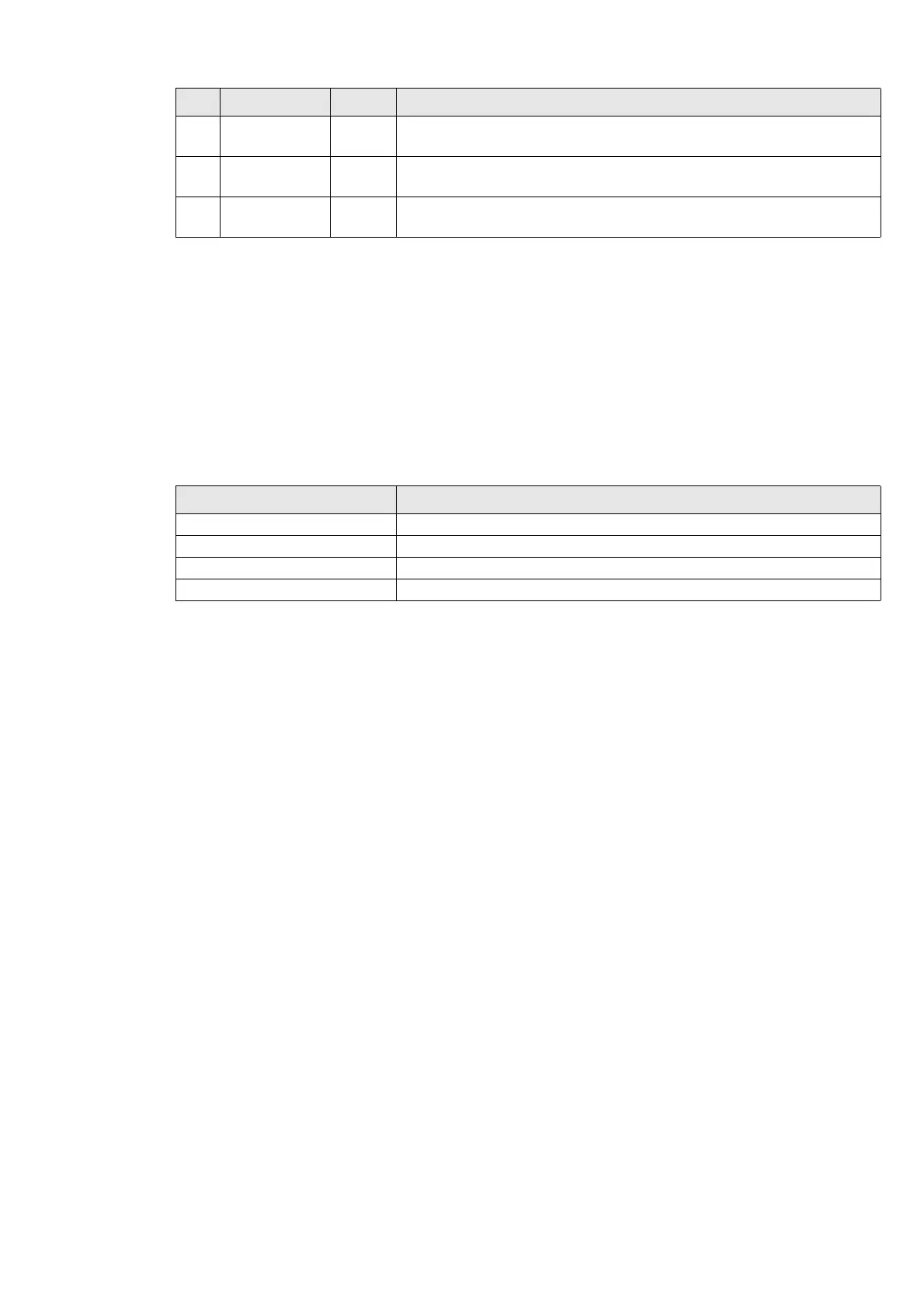
Command Explanation
power on
Switch target power on
power off Switch target power off
power on perm Set target power supply default to "on"
power off perm Set target power supply default to "off"
Table 16.11: Command List
PIN SIGNAL TYPE Description
Table 16.10: 19-pin JTAG/SWD and Trace pinout