J-Link / J-Trace (UM08001) © 2004-2017 SEGGER Microcontroller GmbH & Co. KG
377
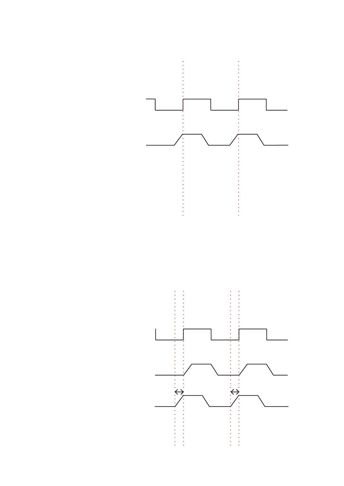
As can be seen in the following drawings, by moving the sampling point of the TDx
signal, a setup time for the trace data is generated (
Δt
d
). This can be used to enable
tracing on targets that do not provide a setup time for the trace data.
Drawing a) shows the correct behaviour of a target and b) shows a target that does
not apply setup times. Therefore in b) the undelayed signal TDx would be sampled as
a logical 0 at the rising edge of TCLK which would give the J-Trace wrong tracing
information. In the case where the sample point of TDx is moved to the left (nega-
tive) by
Δt
d
at each rising TCLK edge a logical 1 is sampled which in this case means
that the J-Trace now recieves the correct trace information.
a)
TCLK
TDx
TCLK
TDx
TDx + Δt
d
Δt
d
Δt
d
b)