422 CHAPTER 16 Target interfaces and adapters
J-Link / J-Trace (UM08001) ©
2004-2017 SEGGER Microcontroller GmbH & Co. KG
16.1.2.1 Target board design
We strongly advise following the recommendations given by the chip manufacturer.
These recommendations are normally in line with the recommendations given in the
table
Pinout for SWD on page 421. In case of doubt you should follow the recommen-
dations given by the semiconductor manufacturer.
16.1.2.2 Pull-up/pull-down resistors
A pull-up resistor is required on SWDIO on the target board. ARM recommends 100
kOhms.
In case of doubt you should follow the recommendations given by the semiconductor
manufacturer.
16.1.2.3 Target power supply
Pin 19 of the connector can be used to supply power to the target hardware. Supply
voltage is 5V, max. current is 300mA. The output current is monitored and protected
against overload and short-circuit.
Power can be controlled via the J-Link commander. The following commands are
available to control power:
Command Explanation
power on
Switch target power on
power off Switch target power off
power on perm Set target power supply default to "on"
power off perm Set target power supply default to "off"
Table 16.4: Command List
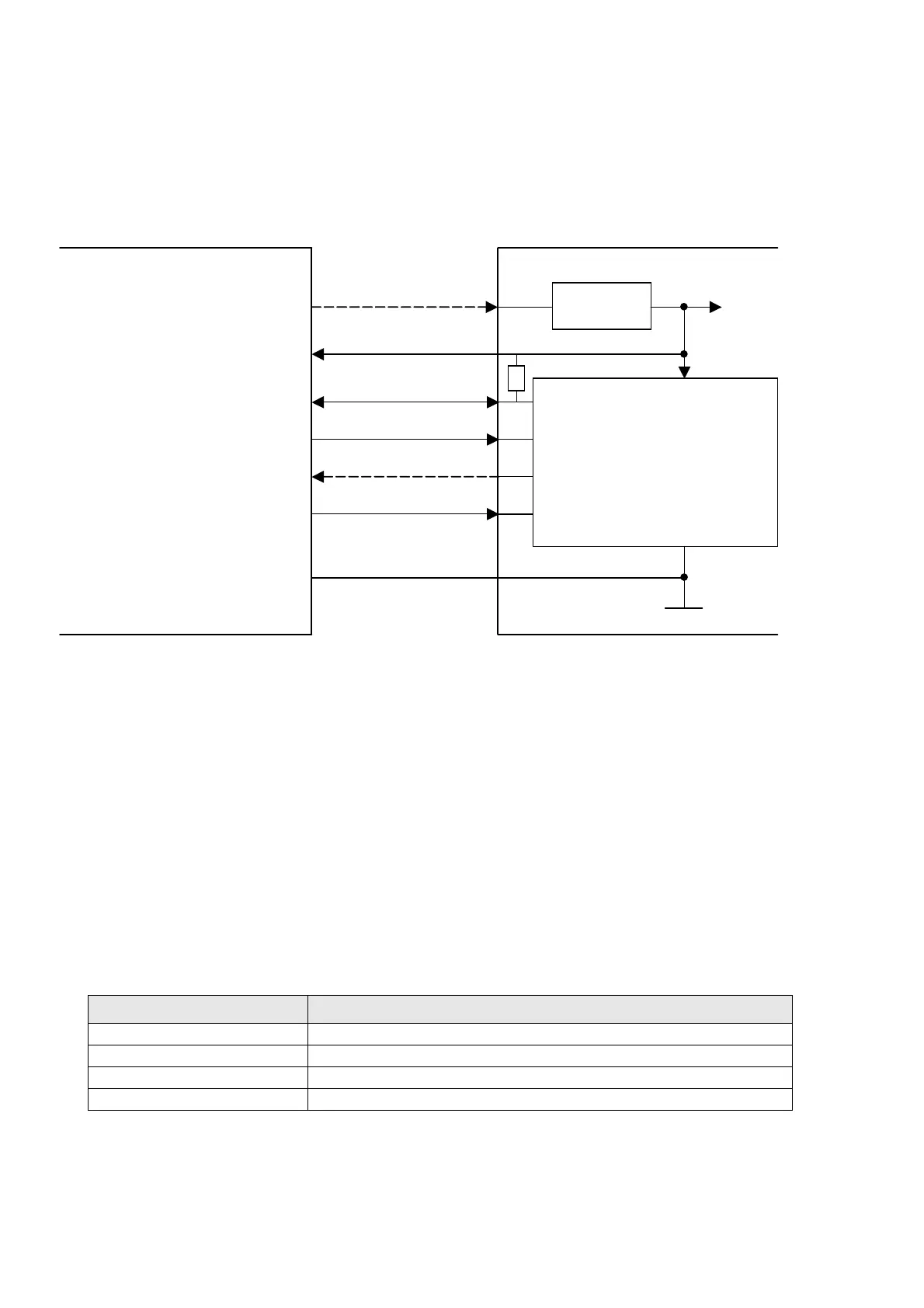
Typical target connection for SWD
JTAG connector
Target board
SWDIO
SWCLK
SWO
RESET
CPU
SWDIO
SWCLK
SWO
nRST
GND
Voltage
Regulator
VCC
VCC
5V supply
VTref
GND
7
9
13
15
* Optional to supply the target board from J-Link.
1
19*
7
9
13
15
1
19
J-Link
20 20
100 k