J-Link / J-Trace (UM08001) © 2004-2017 SEGGER Microcontroller GmbH & Co. KG
429
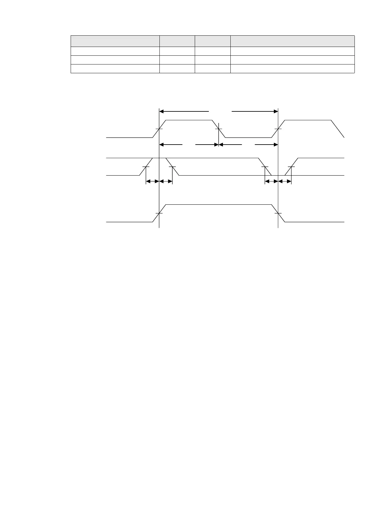
The diagram below shows the TRACECLK frequencies and the setup and hold timing
of the trace signals with respect to TRACECLK.
Note: J-Trace supports half-rate clocking mode. Data is output on each edge of
the TRACECLK signal and TRACECLK (max) <= 100MHz. For half-rate clocking, the
setup and hold times at the JTAG+Trace connector must be observed.
Thh 1.5ns - Data hold high
Tsl 2.5ns - Data setup low
Thl 1.5ns - Data hold low
Parameter Min. Max. Explanation
Table 16.9: Clock frequency
Tperiod
Tch Tcl
Tsh Thh Tsl Thl
Full
TRACECLK
Half-rate
TRACECLK
DATA