Recorded data is expressed in internal drive unit (analog-to-digital converter counts).
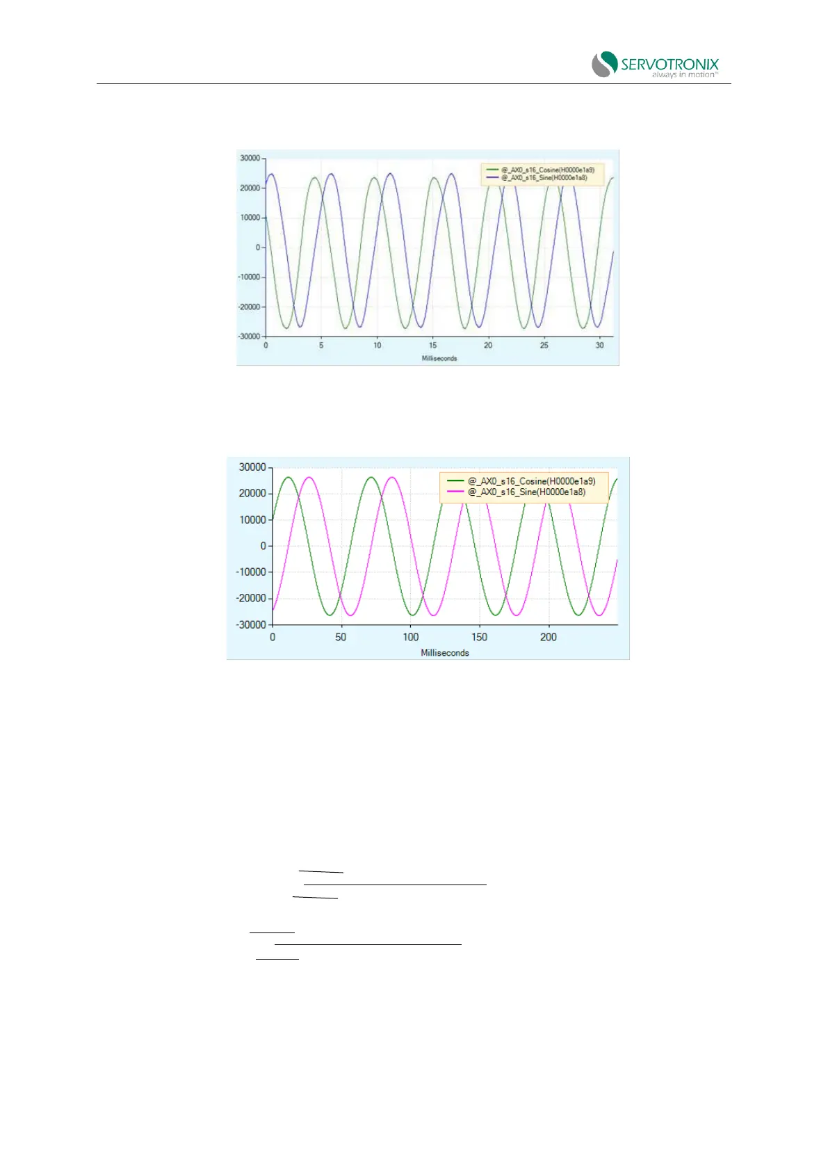
Figure 6-22 Sine encoder recording - example
A typical resolver record might look like the figure below.
Figure 6-23 Resolver recording - example
Converting to physical value
The recorded data is expressed in internal drive unit and needs to be converted to physical
unit; i.e. drive input voltage.
Since the physical sine and cosine signal scales of the sine encoder and resolver are different,
the following equation is used to convert the recorded data:
Sine encoder: input voltage