When checking the sine and cosine signals of the sine encoder, you need to calculate as: signal
10/16.2 x (1/32768 0.00001883×
).
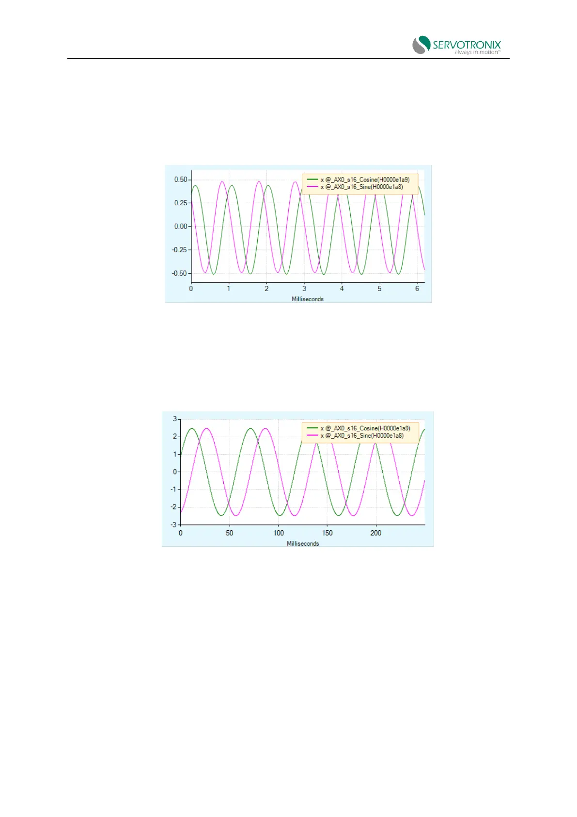
The resulting data diagram in the Rang screen will look similar to the figure below. This diagram
shows the signal level (expressed in volts) of the actual input signal. As expected, the sine encoder
signal is close to 1V peak-to-peak.
Figure 6-24 Sine encoder signal - example
When checking the sine and cosine signals of the resolver, you need to calculate as: signal
10/3.25 x (1/32768 0.0000939×
).
The resulting diagram in the Rang screen will look similar to the figure below. This diagram
shows the signal level (expressed in volts) of the actual input signal.
Figure 6-25 Resolver signal - example
6.6 Secondary feedback
Please also refer to Dual Feedback Position Control Loop Tuning.
6.6.1 Overview of secondary feedback (dual loop control)
CDHD2S can correct positioning error through secondary feedback device and dual-loop
control.