In addition to tuning the current, velocity, and position loops, the following table shows some
of the parameters used to configure and monitor the gearing.
Table 7-6
7.6.1 Pulse and direction
In "pulse and direction" position control, the drive is synchronized to a main input command
signal in the form of a pulse train.
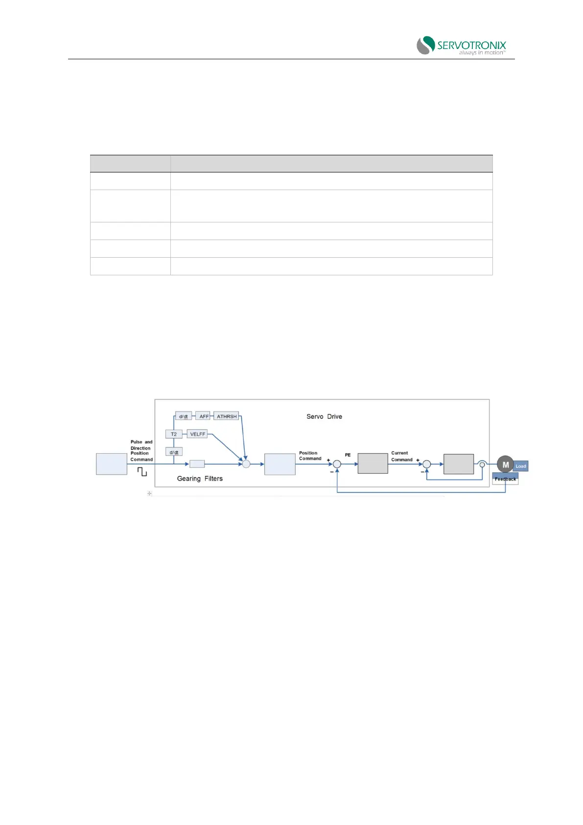
Figure 7-8 Pulse and direction position control
The drive receives each rising edge of the pulse to increase (or decrease, depending on the
direction) the external input position counter (HWPEXT) of the drive by one position count. This
counter value is transmitted through the gearing module and becomes the motor position
command.
Compare the position command and the motor position (PFB) to determine the position error
(PE). The drive corrects the position error by incrementing the motor to the commanded position.
In the "pulse and direction" mode, if the absolute value of GEARIN is equal to GEAROUT, and
XENCRES is equal to 4×MENCRES (i.e. the resolution of the motor encoder after quadrature), then
one input pulse is equivalent to one motor feedback count.