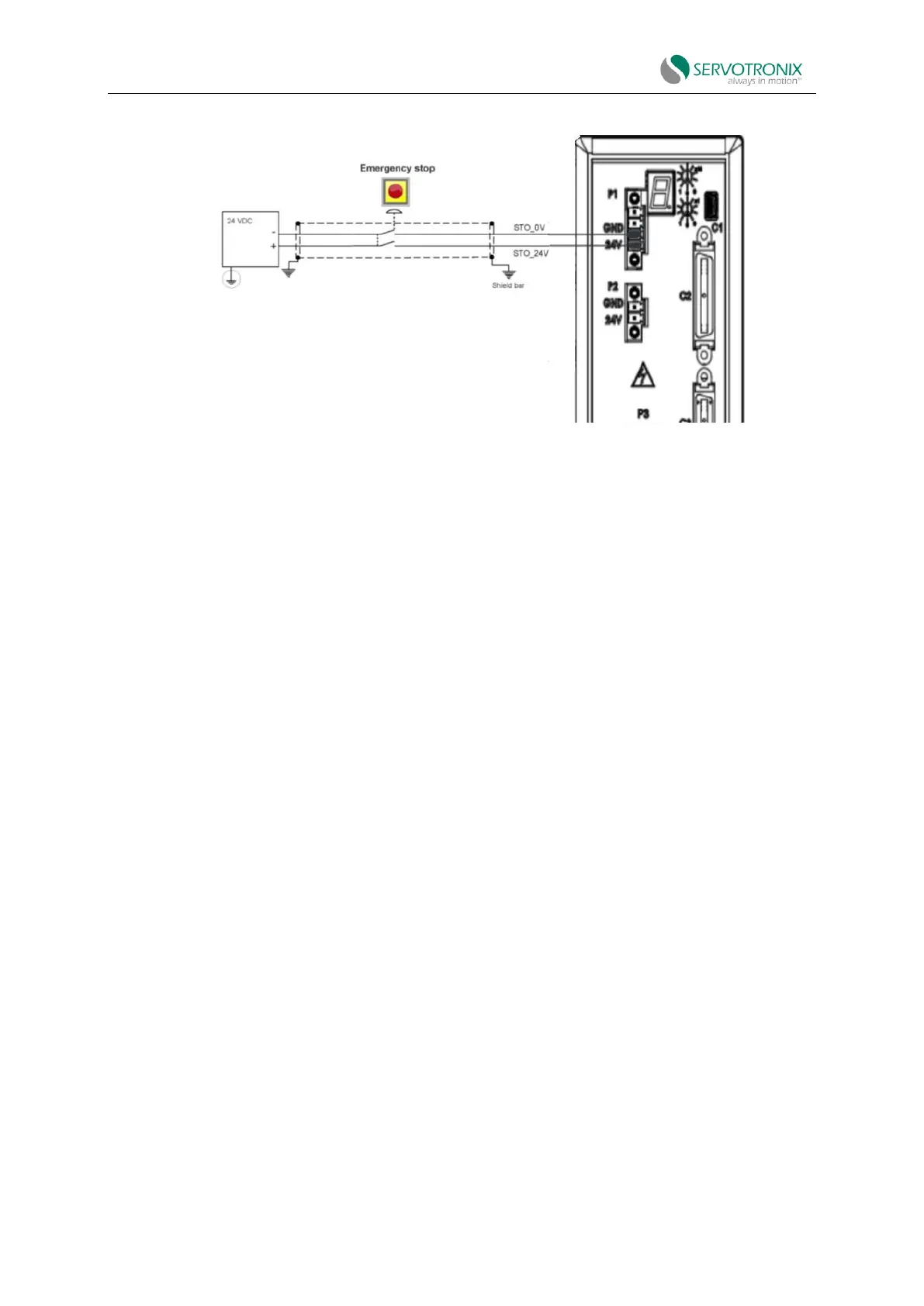
Figure 4-39 STO-emergency stop circuit wiring - example
4.10.3 Motor power - P2, P4
The motor power interface and connector vary with CDHD2S model.
Please refer to the power board pin assignment diagram.
4.10.4 Regenerative Resistors - P3, P5
The regenerative resistance interfaces and connectors of CDHD2S models are different.
Please refer to the power board pin assignment diagram.
If the application requires a regenerative resistor, connect the regenerative resistor between
terminals B1+ and B2.
4.10.5 AC input - bus power and logic power - P3, P4, P5
The AC input interface and connector vary with CDHD2S model.
On the CDHD2S-1D5 and CDHD2S-003, the regeneration and AC input voltages are combined
on one connector. Since these models only support single-phase AC, they do not have an L3
terminal for bus power.
Please refer to the power board pin assignment diagram.
Ensure that the main voltage rating meets the drive requirements. Applying an incorrect
voltage may cause the drive to malfunction. Do not turn on the power supply until all hardware
connections are completed.
Protect against impact surges:
Bus power (L1-L2-L3): When the bus is powered on, wait for 1 minute before turning it on,
whether it is off or not.