⚫ Cycle configuration: Trigger output based on the fixed feedback count between
positions.
⚫ Table configuration: Trigger output based on the predefined position group.
⚫ Timing configuration: trigger output when there is a time offset with the SYNC0 signal.
The controller updates the time offset every cycle.
Note: When using the incremental feedback device, it must be homing before setting any
PCOM module parameters.
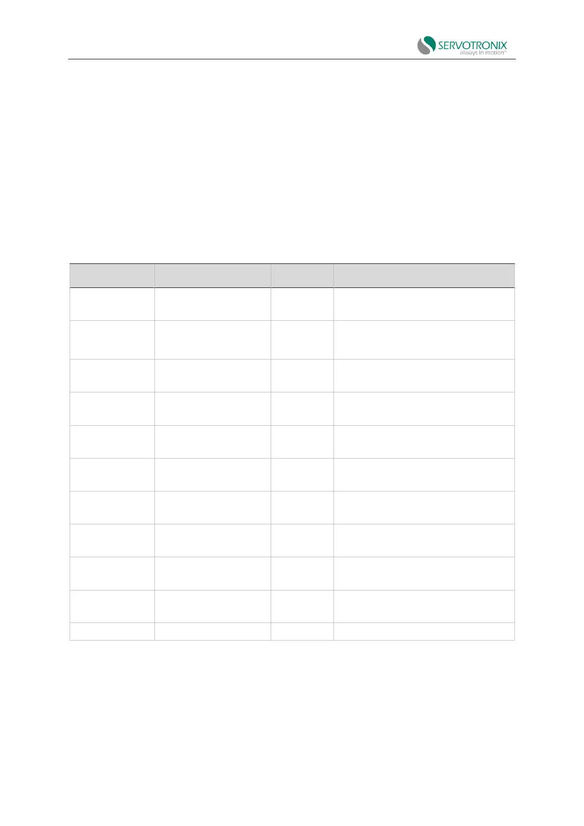
The following parameters are used to configure and monitor the PCOM module.
Table 6-16
Configure and match comparison trigger
output (PCOM) module.
Define whether the motor triggers the
output when it moves in negative, positive
or any direction.
Position of PCOM module to stop triggering
output.
Fixed number of feedback counts between
each output trigger position.
Position of PCOM module to start triggering
output.
Actual state of PCOM module.
A set of positions to be triggered for output.
Number of positions in the PCOM table
Pulse output signal width.
Differential (RS422) digital port hardware and
output function.
Output triggered by PCOM module 1|2
6.11.1 PCOM fixed cycle configuration
The cycle configuration is used to output pulses or switch output states at fixed intervals
(defined as a set of position feedback counts (PCOMN)). In this mode, the PCOM module