6.18.6 Gantry setup
When setting up a CDHD2S gantry system, perform the following steps:
1. If the gantry system includes limit switches, ensure they are installed as follows:
◼ The positive limit switches on Y1 and Y2 must be parallel, and the alignment
deviation must not be greater than 5mm.
◼ The negative limit switches on Y1 and Y2 must be parallel, and the alignment
deviation must not be greater than 5mm.
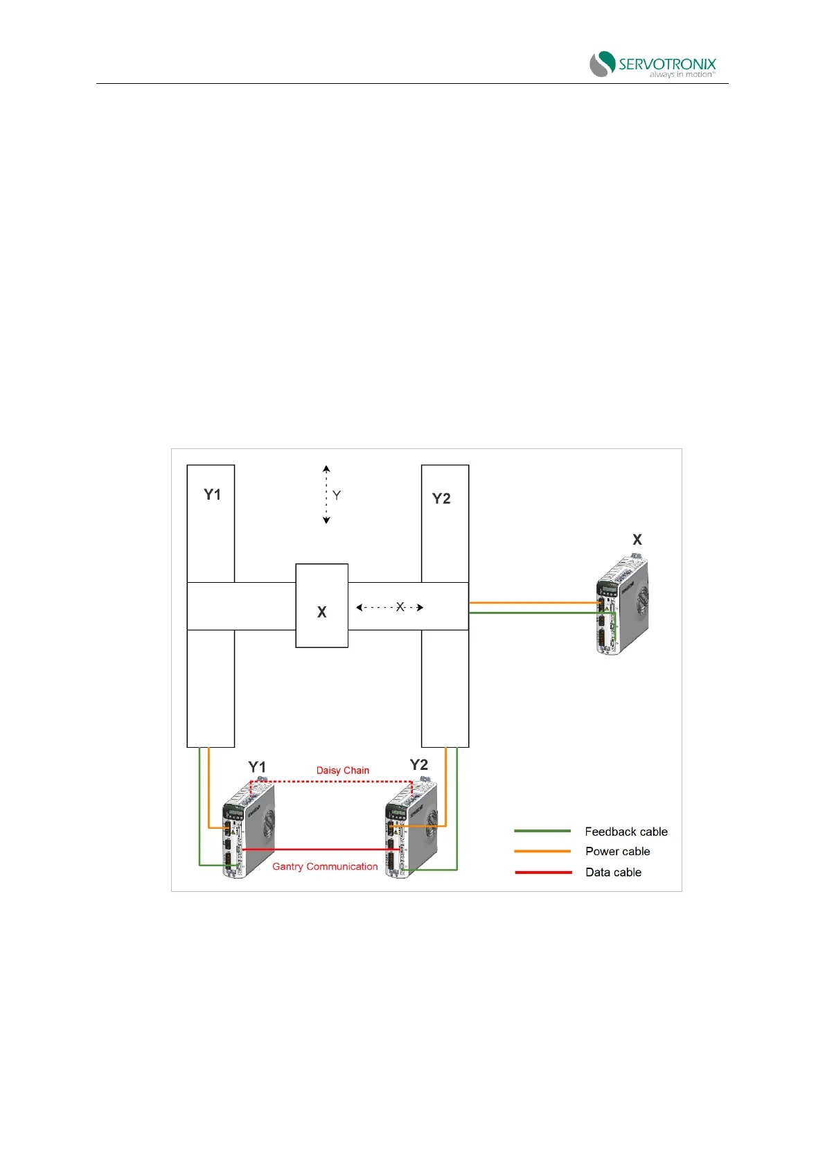
2. Connect the motor of the first gantry axis to the first drive, and connect the second motor
to the second gantry drive. Make sure each pair of power and feedback cables is connected to the
right drive.
Figure 6-59 Gantry wiring and communication
3. Gantry drives are connected to each other through two interfaces, C3 and C8. Fast
communication between axis drives requires C3 connectors.
Parameter configuration and tuning require C8 daisy chain wiring.