4.9.7 Machine interface - C3
Note: EB model - CDHD2SEB model has no machine interface.
Wire machine inputs and outputs according to your application requirements.
Unused pins must remain unwired.
The common inputs and common outputs on the controller interface (C2) and machine
interface (C3) are connected internally.
The DC voltage 24V power supply and loop can be connected at the controller interface (C2)
or the machine interface (C3), but not both.
All digital inputs and digital outputs on all CDHD2S models are optoisolated.
Fast output can only be sink type. All other digital inputs and digital outputs can be connected
as source or sink.
If both the fast digital output and the regular digital output are configured as sink type, it is
usually possible to use one power supply for all outputs.
It is recommended to use fast output (7 or 8) as the motor brake release signal.
The motor brake requires a separate power supply. If the load is inductive (such as a relay), an
external flywheel diode must be added.
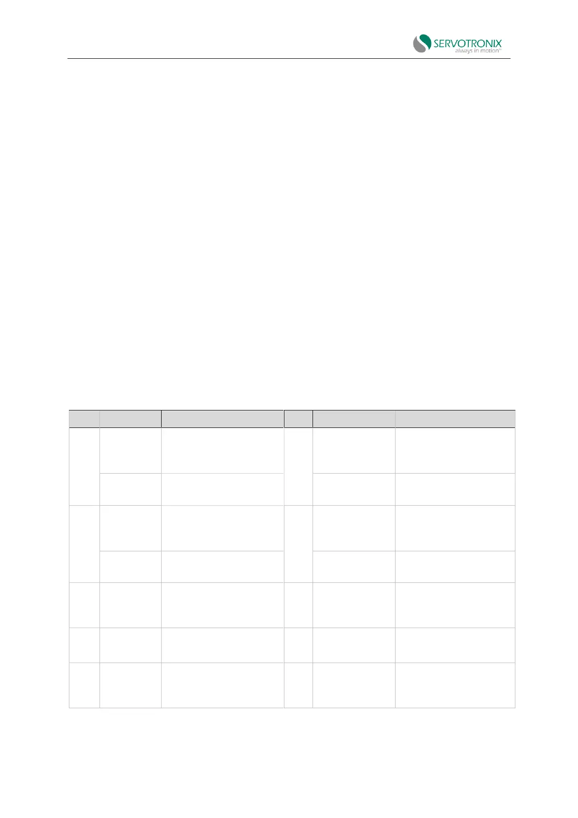
Table 4-13 Machine interface - AP/AF/EC mode