6.17.6 Error correction settings
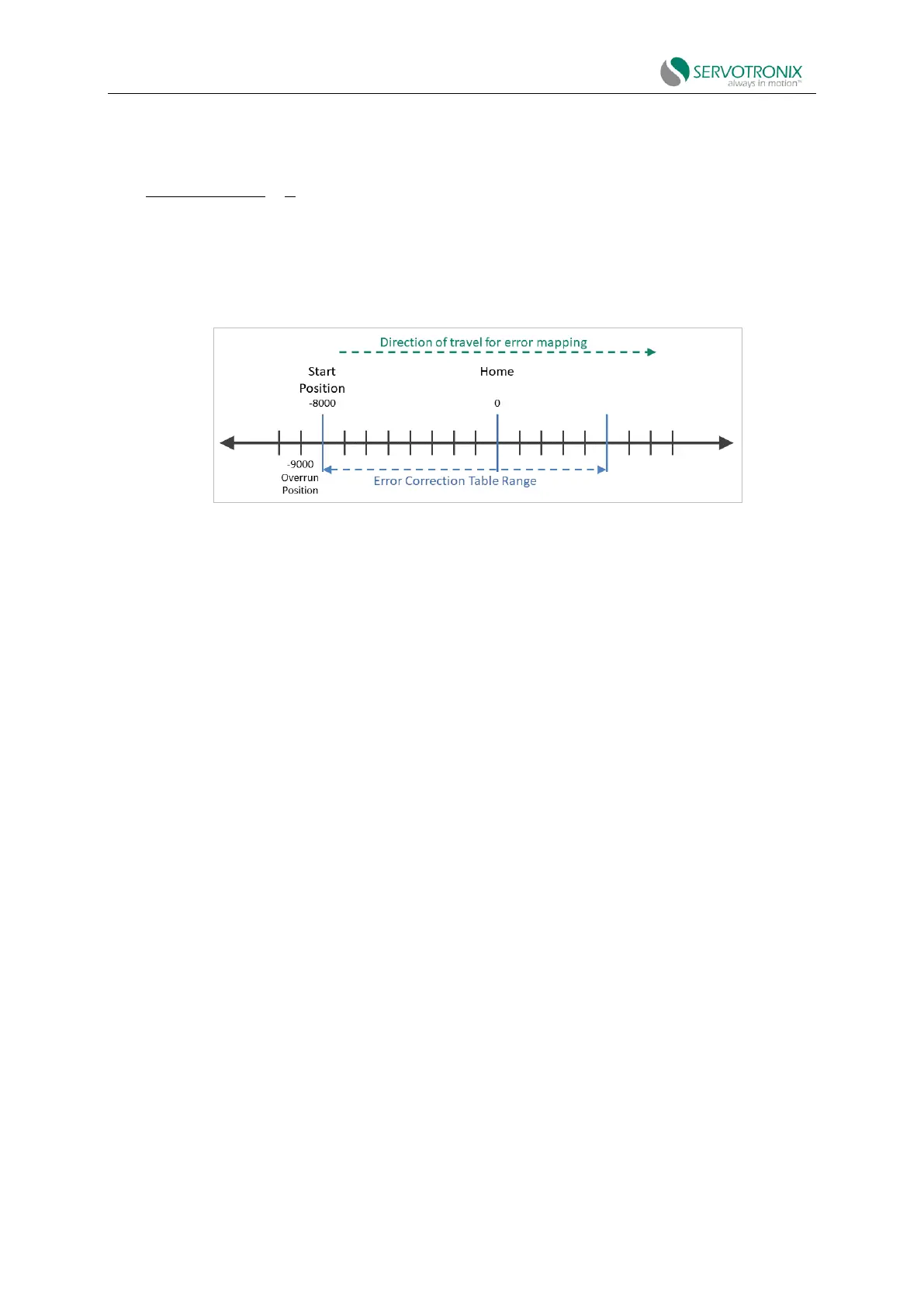
The following figure shows the parameters used by the error correction map.
Figure 6-45 Error correction map - example
Procedure: Manual configuration and generation of error correction table
Use ServoStudio2 adn any measuring device
1. In the ServoStudio2 Error Correction screen, enter the position range settings and setting
values for error sampling and correction.
◼ Start position
◼ Number of sampling points
◼ Interval (sampling point spacing)
◼ Calibration unit (if required)
◼ Load/motor mechanical ratio (if required)
2. Move the motor to a position that is at least a few millimeters away from the start position
(start point) of the error correction table.
3. Move the motor to the start position, and then to several positions consistent with the
positions and intervals defined by ServoStudio2.
4. Using a measurement device, perform error correction measurements at each designated
position and generate a set of error correction values.
5. In the ServoStudio2 correction table, the index and position values will be displayed based
on the values entered on the right side of the screen. Manually enter the correction value for each
position, calculated as follows:
6.
7.
8.