Select controllerI/F optoisolated and pulse and direction (P&D) options. This option will
automatically set the definition for digital inputs 5 and 6.
Step 3 - Digital inputs 5 and 6 setup (optoisolated inputs only)
1. Enter the "Drive Configuration > Digital IO" screen.
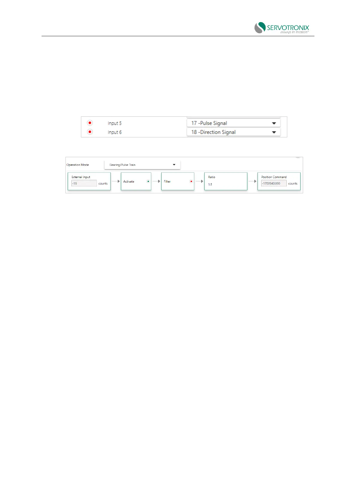
2. Make sure digital input 5 is set to a 17-pulse signal.
3. Make sure digital input 6 is set to the 18-directional signal.
Figure 7-10 Digital input of pulse and direction signals
Step 5 - Set pulse and direction parameters
Figure 7-11 Pulse and direction operation parameters
1. Make sure gearing mode is enabled (GEAR=1).
2. In the Ratio tab, set the input resolution and gear ratio.
The relationship between input pulse and motor shaft motion is determined by the external
encoder resolution (HWPEXT) and the gear ratio (GEARIN/GEAROUT).
For example: Set the PLC controller to provide 1024 line pulses as a CDHD2S system input
command to make the motor rotate two turns. The settings should be as follows:
External encoder resolution=1024
Gear ratio multiplier = 2
Gear ratio divisor=1
3. In the Filter tab, set and adjust the gear filter and command smoothing filter as needed.
Command smoothing filter
◼ Smoothing filter (MOVESMOOTHMODE). Select this option to activate the filter.
◼ Hard/Soft (MOVESMOOTHAVG). Drag the slider to adjust the value.
◼ Gear command smoothing filter
◼ Gear noise filter (GEARFILTMODE). Select this option to activate the filter.
◼ Hard/Soft(GEARFILTDEPTH). Drag the slider to adjust the value.