9.2 Connecting the System Controller and Components
9-19
CBM-20A/20Alite
9
9.2.7 Sub-controller Connection and Setup
It is possible to control a solenoid valve or degassing unit from the CBM-20A by connecting a
sub-controller vp, Option Box vp, Option Box L or Valve Interface. Up to 2 of these
components can be controlled from the CBM-20A.
For details on connections and settings, refer to the component instruction manual.
DIP Switch Settings
Before connecting the CBM-20A to the component, make the necessary DIP switch settings
at the components.
The procedure for Option Box vp is described below as an example.
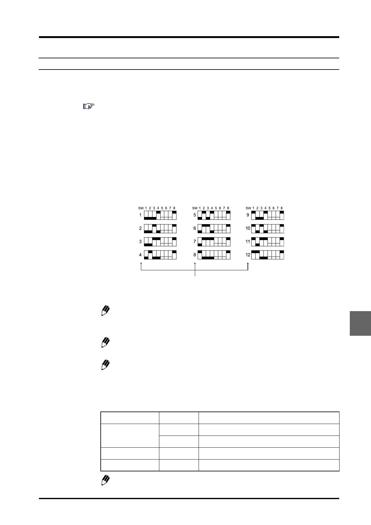
1
Set the channel number for the remote connector (REMOTE) on the system controller
to which the component is connected using pins SW1 to SW4 of the "8-position DIP
switch".
Fig. 9.16
The component can be connected to the remote connector for a channel number
from 1 to 8 (1 to 12 if the optional CBM OPT-4 Optical-connector Expansion Board
is mounted).
DIP switch setup is performed in the same way for Sub-controller vp, Option Box
L, and Valve Interface.
If two sub-controllers are connected, the system controller recognizes them as
sub-controllers A and B in order of increasing channel number.
2
Set pins SW5 to SW8 of the "8 position DIP switch" according to the system
configuration.
Do not set both SW5 and SW6 to ON.
Item Number Remark
SV-TYPE
SW5 Set to ON if the FCV-10AL (vp) is used.
SW6 Set to ON if the FCV-11AL (S) or FCV-15AL is used.
DEGAS SW7 Set to ON if the DGU-10A/B is used.
MODE SW8 Always set to ON when connecting to the CBM.
Number of CBM-20A channel to which
sub-controller vp connected.