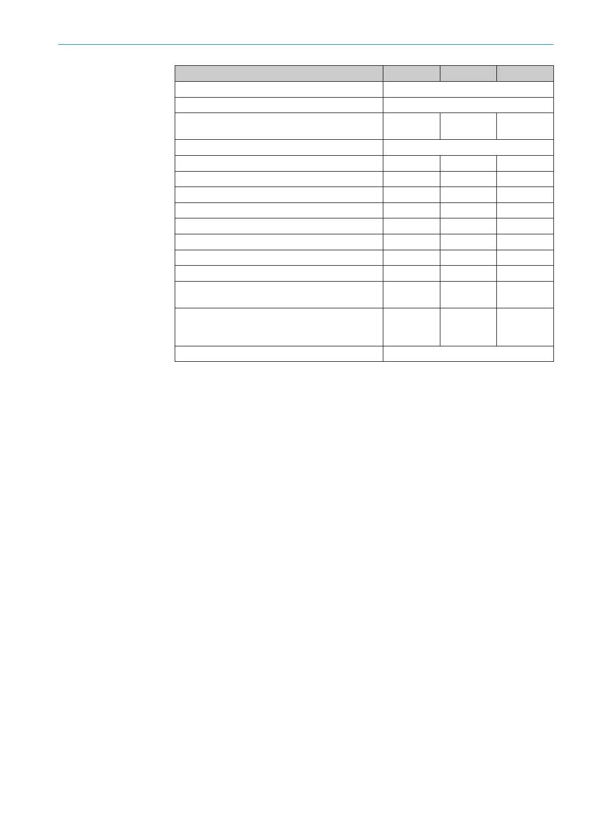
Minimum Typical Maximum
Communication protocol RS-232 (proprietary)
Transmission rate 38,400 Baud
Cable length for 38,400 Baud and 0.25 mm²
c
ables
15 m
Galvanic separation No
Output TxD HIGH 5 V 15 V
Output TxD LOW –15 V –5 V
Voltage range RxD –15 V 15 V
Switching threshold RxD LOW –15 V 0.4 V
Switching threshold RxD HIGH 2.4 V 15 V
Short-circuit current at TxD –60 mA 60 mA
Maximum voltage level at RxD –15 V 15 V
Maximum voltage level at TxD –11 V 11 V
Safe SICK device communication via EFI/SDL
(S300 Mini R
emote only)
Cable length for 500 kBaud (only pre-assembled
extension cables permitted, see table 35,
page 123)
20 m
Galvanic separation No
1)
Operation only in a short-circuit protected system with max. 8 A.
2)
To meet the requirements of the relevant product standards (e.g., IEC 61496-1), the external voltage sup‐
pl
y for the devices must be able to bridge a brief mains failure of 20 ms. Power supply units according to
EN 60204-1 satisfy this requirement. Suitable power supply units are available as accessories from
SICK.
3)
The absolute voltage level must not drop below the specified minimum voltage.
4)
The load currents for the input capacitors are not taken into account.
5)
With a typical supply voltage of 24 V.
6)
Applies to the voltage range between U
s
and 0 V.
7)
Switching currents up to 500 mA are allowed briefly (≤ 100 ms).
8)
In the case of a fault (0 V cable open circuit), no more than the specified leakage current flows in the
O
SSD cable. The downstream control element must detect this status as LOW. An FSPLC (fail-safe pro‐
grammable logic controller) must be able to identify this status.
9)
Make sure to limit the individual conductor resistances to the downstream controller to this value to
ensure that a cross-circuit between the outputs is safely detected. (Also note EN 60204-1.)
10)
When active, the outputs are tested cyclically (brief LOW). When selecting the downstream controllers,
make sure that the test pulses do not result in deactivation.
12 T
ECHNICAL DATA
112
O P E R A T I N G I N S T R U C T I O N S | S300 Mini 8014170/ZA23/2019-11-14 | SICK
Subject to change without notice