Capitolo 5 Istruzioni d’uso
TR4
232 © SICK AG • Industrial Safety Systems • Germania • Tutti i diritti riservati 8014467/YTD7/2016-03-30
Contenuti soggetti a modifiche senza preavviso
Installazione elettrica
it
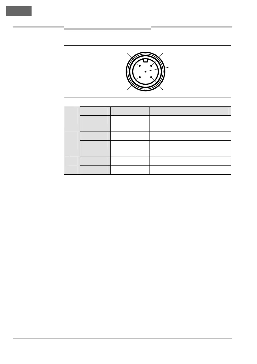
5.3.2 Spina di allacciamento del sensore M12 × 5
Pin Colore filo
2)
Denominazione Descrizione
1 Marrone +24 V cc Alimentazione di tensione di
24 V cc
2 Bianco 0ut A Uscita di sicurezza A
3 Blu 0 V Alimentazione di tensione di
0 V cc
4 Nero 0ut B Uscita di sicurezza B
5 Grigio Out Aux Uscita Aux (non sicura)
2)
I colori indicati valgono per l’impiego di cavi di allacciamento preassemblati
(senza garanzia).
Fig. 6: assegnazione
dei pin nella spina di
allacciamento del
sensore M12
×
5 (TR4-
S..02C)
Tab. 3: assegnazione
dei pin nella spina di
allacciamento del
sensore M12
×
5 (TR4-
S..02C)
1
4
2
5
3