Chapter 5 Operating Instructions
TR4
76 © SICK AG • Industrial Safety Systems • Germany • All rights reserved 8014467/YTD7/2016-03-30
Subject to change without notice
Electrical installation
en
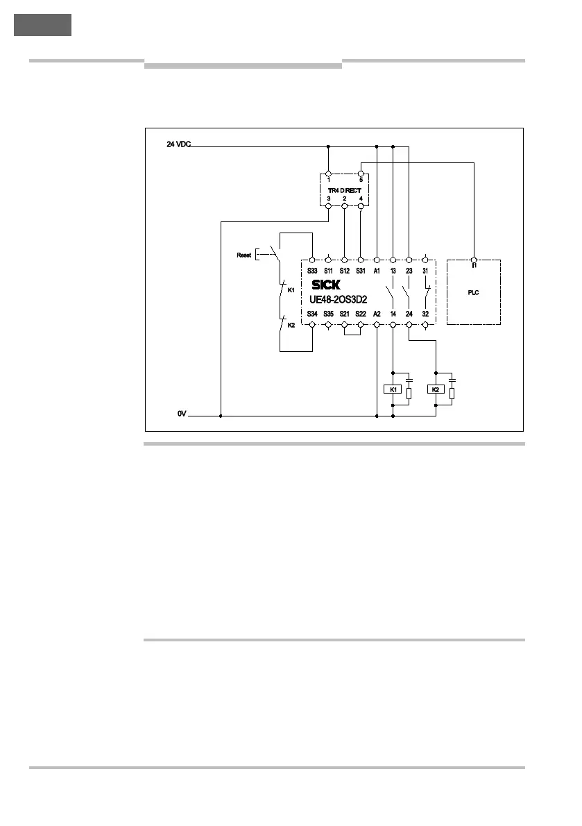
5.3.3 Connection of a single safety switch
= Connect the safety switch as shown in Fig. 7.
Use external device monitoring!
The TR4 has no external device monitoring. To achieve SIL3/PL e you
must therefore implement external device monitoring with the aid of
suitable higher level safety evaluation.
The actual performance level or safety integrity level achieved depends
on the external circuit, the design of the wiring, the selection of the con-
trol switch and its placement on the machine.
Evaluate both safety outputs!
To ensure safety it is imperative you evaluate both safety outputs
(Out A and Out B) (see Fig. 7).
Fig. 7: Connection of a
single TR4-S..02C safe-
ty switch (with M12
×
5
connection plug)
WARNING