Chapter 3 Operating Instructions
TR4
66 © SICK AG • Industrial Safety Systems • Germany • All rights reserved 8014467/YTD7/2016-03-30
Subject to change without notice
Product description
en
3.3 LED indicators
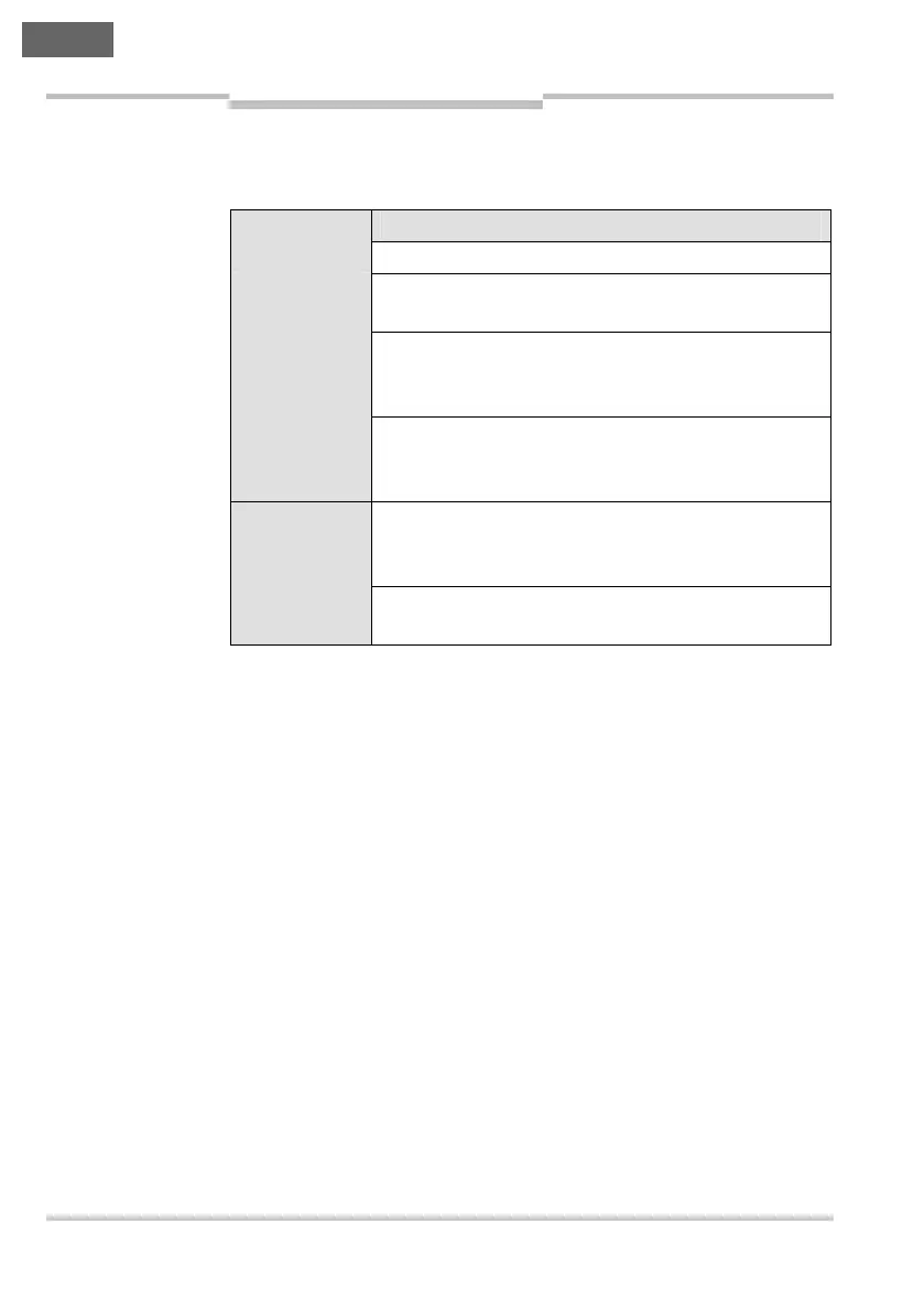
The Status/Diag LED signals the operational status of the TR4.
Display Meaning
ν Off No supply voltage
3 × ∏ Green,
1 × ∏ Red
Power-up sequence
Ν Green Actuator inside the response range,
safety outputs active,
application diagnostic output Aux inactive
Ν Red Actuator outside the response range,
safety outputs inactive,
application diagnostic output Aux active
∏ Yellow Sensor is approaching the maximum response
range (boundary area indication, only on the
TR4-SExxxx and TR4-SFxxxx)
∏ Red or
∏ Green
Error. See Tab. 5 “Error displays of the Status/Diag
LED” in section 8.3 on page 89.
For further LED displays see Tab. 4 “Error displays of the Status/Diag
LED on the TR4 Unique Coded during teach-in” on page 83 and Tab. 5
“Error displays of the Status/Diag LED” on page 89.
Tab. 1: LED displays of
the TR4
Ν The LED is
illuminated
constantly.
∏ The LED is flashing.
ν The LED is off.