Operating Instructions Chapter 8
TR4
8014467/YTD7/2016-03-30 © SICK AG • Industrial Safety Systems • Germany • All rights reserved 89
Subject to change without notice
Fault diagnosis
en
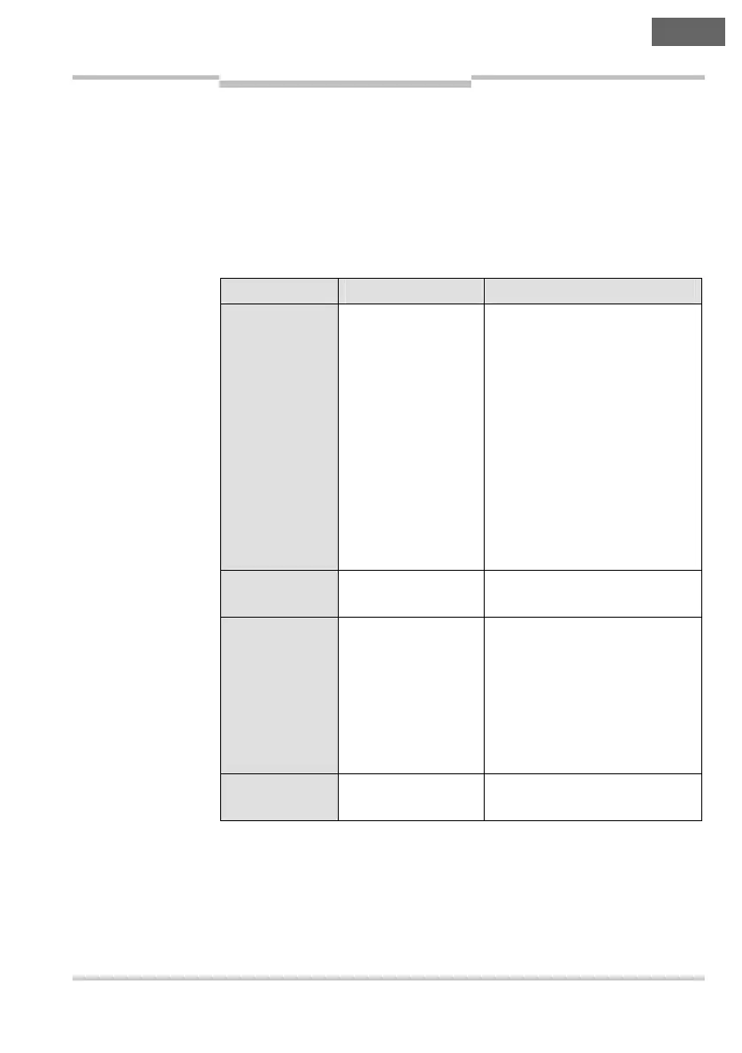
8.3 Error displays of the Status/Diag LED
This section explains the meaning of the error displays of the
Status/Diag LED and how to respond to the messages. Please refer to
section 3.3 “LED indicators” on page 66 for a description.
Please refer to section 6.2.3 “Error displays of the TR4 Unique Coded
during teach-in” on page 83 for a description of the error messages
during teach-in mode.
Display Possible cause Rectification of the error
∏ Green Power-up test
or
Signal on the OSSD
inputs In A and In B
invalid or not
present
= Wait until the device has
completed the power-up
test.
= Check the voltage supply
(24 V DC) and the OSSD
inputs In A and In B (red
and yellow wires).
= In case of cascaded safety
switches, check whether all
actuators are in the
response range of the
related sensors.
Ν Red Actuator outside
the response range
= Move the actuator into the
response range.
∏ Red (1 Hz) Recoverable error = Check the OSSDs for short-
circuit to 0 V, 24 V DC or to
each other.
= Disconnect the voltage
supply to the device for at
least 3 seconds to reset the
device.
∏ Red (4 Hz) Unrecoverable
error
= Replace the device.
Tab. 5: Error displays of
the Status/Diag LED