EasyManuals Logo

SICK TR4 User Manual

SICK TR4
Go to English
264 pages
To Next Page IconTo Next Page
To Previous Page IconTo Previous Page
Page #75 background imageLoading...
Page #75 background image
Operating Instructions Chapter 5
TR4
8014467/YTD7/2016-03-30 © SICK AG • Industrial Safety Systems • Germany • All rights reserved 75
Subject to change without notice
Electrical installation
en
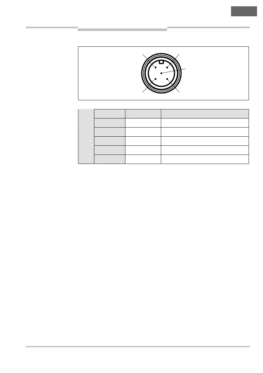
5.3.2 M12 × 5 sensor connection plug
Pin Wire color
2)
Designation Description
1 Brown +24 V DC Voltage supply 24 V DC
2 White 0ut A Safety output A
3 Blue 0 V Voltage supply 0 V DC
4 Black 0ut B Safety output B
5 Gray Out Aux Aux output (not safe)
2)
The stated colors apply on the usage of pre-assembled cables (should be
checked).
Fig. 6: Pin assignment
sensor connection plug
M12
×
5 (TR4-S..02C)
Tab. 3: Pin assignment
sensor connection plug
M12
×
5 (TR4-S..02C)
1
4
2
5
3

Table of Contents

Questions and Answers:

Question and Answer IconNeed help?

Do you have a question about the SICK TR4 and is the answer not in the manual?

SICK TR4 Specifications

General IconGeneral
Number of Safe Outputs2
Output TypePNP
Protection RatingIP67
TypeSafety Switch
Housing MaterialPlastic
Supply Voltage24V DC
Connection TypeCable
Operating Voltage24 V DC
Operating Temperature-25 °C ... +70 °C
Actuator TypeSeparate actuator (TR4 Direct, TR4 Standard, TR4 Extended)

Related product manuals