Chapter 8 Operating Instructions
TR4
90 © SICK AG • Industrial Safety Systems • Germany • All rights reserved 8014467/YTD7/2016-03-30
Subject to change without notice
Fault diagnosis
en
Display Possible cause Rectification of the error
∏ Yellow
(1 Hz)
Actuator in the
boundary area of
the switch-on
distance; safe
status, OSSD Out A
and OSSD Out B
active
= Re-align sensor and
actuator.
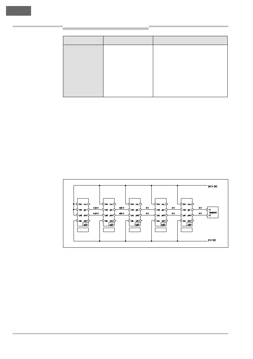
8.4 Troubleshooting in case of cascading
If an error occurs on TR4 safety switches used in a cascade, the related
device indicates the error state (Status/Diag LED flashes ∏ Red) and
switches off its safety outputs. In this case all other downstream TR4
safety switches also switch off their safety outputs and the Status/Diag
LEDs flashes ∏ Green.
The safety switches ahead of a device with an error in the cascade can-
not detect the error state. Their Status/Diag LED continue to illuminate
Ν Green if their actuators are in the response range.
Note
Fig. 13: Troubleshoo-
ting with cascaded
safety switches
Switch 1 Switch 2 Switch 3 Switch 4 Switch 5
Actuator 1 Actuator 2 Actuator 3 Actuator 4 Actuator 5
Ν Green
Ν Green ∏ Red ∏ Green ∏ Green