Operating Instructions Chapter 5
TR4
8014467/YTD7/2016-03-30 © SICK AG • Industrial Safety Systems • Germany • All rights reserved 73
Subject to change without notice
Electrical installation
en
5.3 Connection
Switch the power supply off!
The machine/system could unintentionally start up while you are
connecting the devices.
= Ensure that the entire machine/system is disconnected during the
electrical installation.
Only use a suitable voltage supply!
The sensor must be connected to a voltage supply of protection class 2
SELV 24 V DC, +10 %/–15 %.
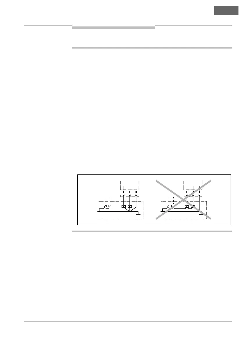
Prevent the formation of a potential difference between the load and
the protective device!
= If you connect loads to the OSSDs that are not reverse polarity pro-
tected, then you must connect the 0 V connections for these loads
and the related protective device separately, one after the other, to
the same 0 V terminal strip. Only then is it ensured that in the case of
a fault, it is not possible for a potential difference to form between
the 0 V connections for the loads and the related protective device.
• The TR4 safety switch meets the interference suppression require-
ments (EMC) for industrial use (interference suppression class A).
When used in residential areas it can cause interference.
• To minimize line effects on the behavior of the device, the external
voltage supply for the devices (SELV) must, among other aspects, be
able to bridge a power failure lasting 20 ms. Power supplies accord-
ing to EN 60 204-1 satisfy this requirement. Suitable power supplies
are available as accessories from SICK.
WARNING
Notes
Out B
Out B