Chapter 5 Operating Instructions
TR4
74 © SICK AG • Industrial Safety Systems • Germany • All rights reserved 8014467/YTD7/2016-03-30
Subject to change without notice
Electrical installation
en
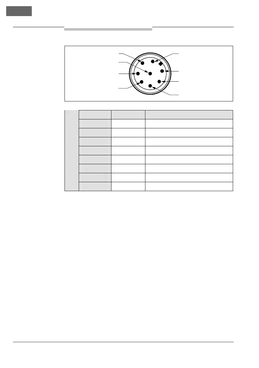
5.3.1 M12 × 8 sensor connection plug
Pin Wire color
1)
Designation Description
1 White Out Aux Aux output (not safe)
2 Brown +24 V DC Voltage supply 24 V DC
3 Green N.c. Not connected
4 Yellow In B Enable input for channel B
5 Gray 0ut A Safety output A
6 Pink 0ut B Safety output B
7 Blue 0 V Voltage supply 0 V DC
8 Red In A Enable input for channel A
1)
The colors stated apply both to the cable variants and on the usage of
preassembled connecting cables for the connector variants
(e.g. DOL-1208-G..MA).
Fig. 5: Pin assignment
M12
×
8 sensor connec-
tion plug (TR4-S..01C)
Tab. 2: Pin assignment
(connector variant) and
wire color (cable vari-
ant) M12
×
8 sensor
connection plug
(TR4-S..01C)
2
1
7
6
3
8
4
5