EasyManuals Logo

SICK TR4 User Manual

SICK TR4
Go to English
264 pages
To Next Page IconTo Next Page
To Previous Page IconTo Previous Page
Page #78 background imageLoading...
Page #78 background image
Chapter 5 Operating Instructions
TR4
78 © SICK AG • Industrial Safety Systems • Germany • All rights reserved 8014467/YTD7/2016-03-30
Subject to change without notice
Electrical installation
en
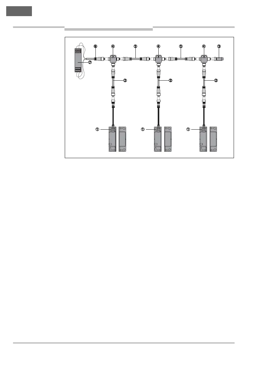
0 Transponder safety switch TR4 Direct
1 Connection cable with M12 male connector, 8-pin and M12
female connector, 8-pin (e.g. DSL-1208-xxxxxx)
2
End plug TR4-AL002C
3 T-piece TR4-AK004C
4 Connection cable with M12 male connector, 4-pin and M12
female connector, 4-pin (e.g. DSL-1204-xxxx)
5
Connecting cable with M12 female connector, 4-pin and flying
leads (e.g. DOL-1204-xxxx)
6
Safe evaluation unit
Fig. 8: Several
TR4-S..01C safety
switches in a cascade

Table of Contents

Questions and Answers:

Question and Answer IconNeed help?

Do you have a question about the SICK TR4 and is the answer not in the manual?

SICK TR4 Specifications

General IconGeneral
Number of Safe Outputs2
Output TypePNP
Protection RatingIP67
TypeSafety Switch
Housing MaterialPlastic
Supply Voltage24V DC
Connection TypeCable
Operating Voltage24 V DC
Operating Temperature-25 °C ... +70 °C
Actuator TypeSeparate actuator (TR4 Direct, TR4 Standard, TR4 Extended)

Related product manuals