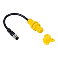
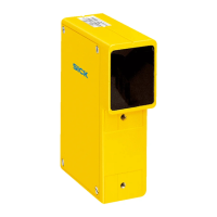
Do you have a question about the SICK TR4 and is the answer not in the manual?
Number of Safe Outputs | 2 |
---|---|
Output Type | PNP |
Protection Rating | IP67 |
Type | Safety Switch |
Housing Material | Plastic |
Supply Voltage | 24V DC |
Connection Type | Cable |
Operating Voltage | 24 V DC |
Operating Temperature | -25 °C ... +70 °C |
Actuator Type | Separate actuator (TR4 Direct, TR4 Standard, TR4 Extended) |
Describes the purpose and scope of the operating instructions for the TR4 safety switch.
Identifies the intended audience for these operating instructions.
Outlines the key topics covered within the document.
Specifies the necessary qualifications for personnel installing and servicing the TR4 safety switch.
Explains the intended use and monitoring functions of the TR4 safety switches.
Details the proper operational guidelines and limitations for the TR4 safety switches.
Provides essential safety instructions for the correct and safe use of the TR4 series switches.
Explains the construction and operating principle of the TR4 safety switch.
Describes series connection and how errors are detected in the TR4 safety switches.
Details the meaning of the Status/Diag LED signals for operational status.
Provides a step-by-step guide for the physical installation of the safety switch.
Highlights critical safety considerations during the mounting process.
Specifies the minimum distance required when installing several safety switches.
Crucial safety information regarding the wiring and evaluation of outputs.
Explains how the safety switch handles various fault conditions.
Details connecting the switch, including different connector types and wiring configurations.
Emphasizes safety checks and timing requirements by qualified personnel.
Explains teaching actuators to Unique Coded safety switches.
Outlines initial and periodic tests and inspections for safe operation.
General guidance on handling malfunctions and errors.
Explains how to interpret LED error codes for troubleshooting.
Specific guidance for diagnosing issues in cascaded systems.
Details the time taken for the switch to react to events.
Comprehensive table of technical characteristics and operating data.
Section dedicated to physical dimensions of the components.
Lists part numbers for various TR4 safety switch models.
Part numbers for ordering replacement actuators.
Part numbers for related accessories, connectors, and cables.
Lists compatible control systems from SICK.
Information on conformity with EU directives and declarations.
An index of all tables included in the document.
An index of all figures and diagrams in the document.