Installing
4.6 Installing Control Unit
Converter with the CU240B-2 and CU240E-2 Control Units
Operating Instructions, 01/2016, FW V4.7 SP6, A5E34259001B AC
91
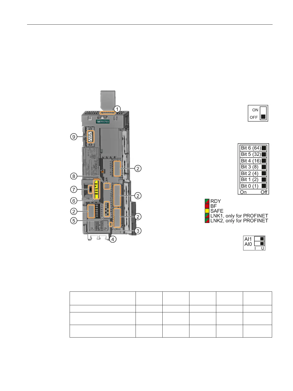
Overview of the interfaces
Interfaces at the front of the Control Unit
To access the interfaces at the front of the Control Unit, you must lift the Operator Panel (if
one is being used) and open the front doors.
Depending on the fieldbus:
USS, Modbus: Bus termination
PROFIBUS, PROFINET,
EtherNet/IP: No function
faces at the lower side
Selecting the fieldbus address
On all Control Units with the
exception of CU240E
-2 PN and
-2 PN-F.
USB interface for connection to a PC
0 and AI 1
1)
(U/I)
I 0/4 mA … 20 mA
U -10/0 V … 10 V
1)
AI 1 is not available on the CU240B-2
Connection to the operator panel
Table 4- 13 Number of inputs and outputs
CU240B-2, CU240B-2 DP 4 1 1 1 0
CU240E-2, CU240E-2 DP,
6 3 2 2 1
CU240E-2 F, CU240E-2 DP-F,
6 3 2 2 3
1)
Every F-DI safe input used occupies two digital inputs DI