Advanced commissioning
6.2 Inverter control
Converter with the CU240B-2 and CU240E-2 Control Units
Operating Instructions, 01/2016, FW V4.7 SP6, A5E34259001B AC
187
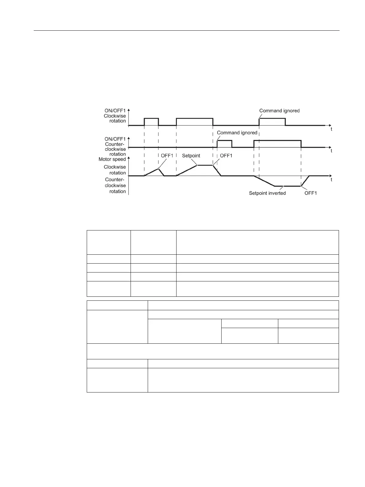
Two-wire control, method 2
You switch the motor on and off using a control command (ON/OFF1) and at the same time
select clockwise motor rotation. You also use the other control command to switch the motor
on and off, but in this case you select counter-clockwise rotation for the motor.
The inverter only accepts a new control command when the motor is at a standstill.
Image 6-7 Two-wire control, method 2
Table 6- 8 Function table
ON/OFF1
clockwise rota-
tion
ON/OFF1 coun-
ter-clockwise
rotation
ON: Clockwise motor rotation.
0 1 ON: Counter-clockwise motor rotation.
1 1 ON: The motor direction of rotation is based on the signal that
assumes status "1" first.
p0015 = 17
Controlling the motor using
the digital inputs of the
inverter:
ON/OFF1 clockwise
ON/OFF1 counter-
Advanced setting
Interconnecting control commands with digital inputs of your choice.
BI: 2/3 wire control command 1 (ON/OFF1 clockwise rotation)
p3331[0 … n] = 722.x
BI: 2/3 wire control command 2
(ON/OFF1 counter-clockwise rotation)
Example: p3331[0] = 722.0 ⇒ if CDS 0 (index[0]) is selected, the inverter
receives its ON/OFF1 counter-clockwise command via DI 0.